bowman1710
Full Member level 3
Hi guys,
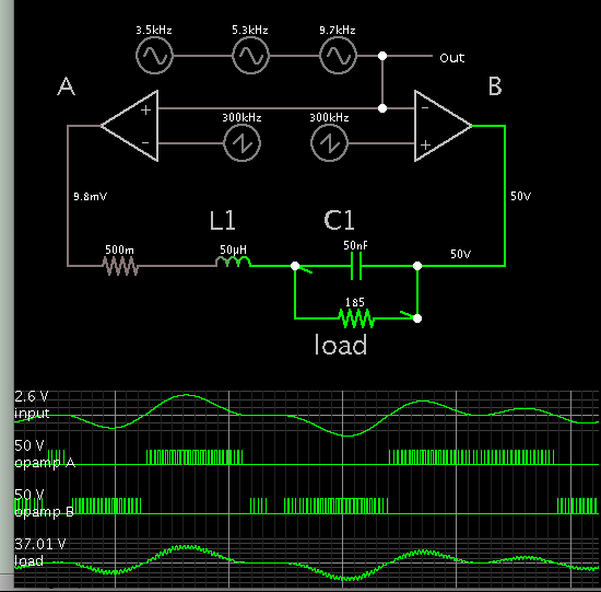
I'm looking at designing a BTL filter for a class D type setup as per attached, links below that are documents I have looked at already.
http://www.ferroxcube.home.pl/appl/info/class D audio amplifier.pdf
http://www.ti.com/lit/an/sloa119b/sloa119b.pdf

Specification:
The PWM signal will be around 300KHz
The sinewave will be 2-20KHz at about 50V p-p
185 ohm load
Really I need the filter to be pretty flat and cut off at about 25-30KHz and really I want as high attenuation as possible at 300KHz, this is where i have a couple of questions
1) What is the best way with this design to achieve this with a high attenuation at 300KHz, would it be a case of higher order filter, if so, how does it work with a BTL design?
2) When designing the inductor how does having a PWM on one leg and a sinewave wave on the other effect the inductors saturation, do you only care about the lower frequency signal and the p-p voltage or is it more complex then that?
Any help would be welcome!
I'm looking at designing a BTL filter for a class D type setup as per attached, links below that are documents I have looked at already.
http://www.ferroxcube.home.pl/appl/info/class D audio amplifier.pdf
http://www.ti.com/lit/an/sloa119b/sloa119b.pdf
Specification:
The PWM signal will be around 300KHz
The sinewave will be 2-20KHz at about 50V p-p
185 ohm load
Really I need the filter to be pretty flat and cut off at about 25-30KHz and really I want as high attenuation as possible at 300KHz, this is where i have a couple of questions
1) What is the best way with this design to achieve this with a high attenuation at 300KHz, would it be a case of higher order filter, if so, how does it work with a BTL design?
2) When designing the inductor how does having a PWM on one leg and a sinewave wave on the other effect the inductors saturation, do you only care about the lower frequency signal and the p-p voltage or is it more complex then that?
Any help would be welcome!