Continue to Site

Welcome to EDAboard.com

Welcome to our site! EDAboard.com is an international Electronics Discussion Forum focused on EDA software, circuits, schematics, books, theory, papers, asic, pld, 8051, DSP, Network, RF, Analog Design, PCB, Service Manuals... and a whole lot more! To participate you need to register. Registration is free. Click here to register now.

FM transmitter electronic circuit problem

Status
Not open for further replies.

MSAKARIM

Full Member level 3
Joined
Jun 2, 2015
Messages
154
Helped
1
Reputation
2
Reaction score
4
Trophy points
1,298
Activity points
2,528
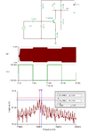
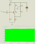
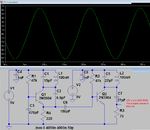
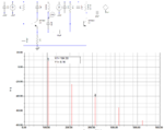
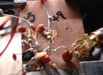
I want to know what is the problem of this electronic circuit ?
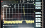
This circuit acts as FM transmitter, when i measured output modulated signal, it gave me zero!

FM.png
 

This circuit will produce AM and FM components as shown below where a 100kHz modulation source is used.
 

Attachments

  • FM_AM.png
    FM_AM.png
    34.4 KB · Views: 92
Are you talking about a physical measurement or some simulation results?
If you are doing a physical measurement, please explain your method.
 

Are you talking about a physical measurement or some simulation results?
If you are doing a physical measurement, please explain your method.

I mean simulation measurements using Proteus.

- - - Updated - - -

Are you talking about a physical measurement or some simulation results?
If you are doing a physical measurement, please explain your method.

How can i attach schematic design file here , if you could check it?
 

You should try and rather use the graph simulation than the virtual oscilloscope for this circuit. Using the scope often causes animation problems if not set up 100% in the animation settings.
 

Attachments

  • FM_AM_proteus.png
    FM_AM_proteus.png
    145.6 KB · Views: 87
Last edited:
Plot that shows the modulation signal as well.
 

Attachments

  • FM_AM_proteus1.png
    FM_AM_proteus1.png
    11.6 KB · Views: 76
It should be obvious that the transistor is saturated and is turned on as hard as it can go. When the circuit uses a regulated 5V supply, R1 is supposed to be 47k, not 4.7k.
My FM transmitter works perfectly and simulates well:
 

Attachments

  • FM transmitter tweaked.png
    FM transmitter tweaked.png
    29.8 KB · Views: 83
Audioguru, I noticed your simulation shows an output power of 280mW into 75 ohm. Have you measured the actual output on a spectrum analyzer? I have found these simple FM transmitters using 2N3904 devices like yours to generate only about 10mW of true RF power when measured on the bench.

Harmonic balance simulators give a more accurate realistic result than the normal SPICE simulators.

For interest, I ran the simulation on your posted circuit, and it gives a result near 10mW (8.16 dBm) into 75 Ohm.
 

Attachments

  • FMTX_HB.png
    FMTX_HB.png
    52.5 KB · Views: 77

I don't see a reason why HB should give more accurate results than transient analysis. There may be however a problem of inaccurate transistor models. Ltspice models are rather basic.

10 mW at 100 MHz sounds low for 2N3904, though.
 

The non-linear models used by HB simulators lend to more accurate simulation results in general as far as my experience.
 

My simulation shows very low distortion so most of its power is in the fundamental frequency.
Your copy of my circuit has a higher value feedback capacitor in the oscillator and does not have a 75 ohm load. I sim'd your copy of my circuit and it is severely distorted.
Editted
 
Last edited:

The feedback capacitor that is a few pF higher won't make any real difference. I had to increase it for the simulator to find a stable oscillation condition. About the load. Do you see the PORT? This is a 75 Ohm port termination.

My question is still if you have verified this claim by actual measurements?
Well, I have on many of these circuits, including yours. The RF into 50 Ohm is only around 2.2Vpp. So in other words around 10dBm or 10mW which agrees very close with the simulator.

I am not speaking from theory but from actual measurements on my bench using a real spectrum analyzer.

- - - Updated - - -

Here is your circuit under test on my bench. SA shows 8 dBm output, the same as the HB simulator.

I am only talking about my measurement results that I have performed on many such FM transmitter circuits.
 

Attachments

  • test_circuit.png
    test_circuit.png
    4.4 MB · Views: 84
  • SA_test_cct.png
    SA_test_cct.png
    9.7 MB · Views: 84

I don't have an oscilloscope that goes up to 1GHz or higher to see actual distortion of 100MHz and I do not have an RF spectrum analyser. So I simulated my circuit and tweaked the parts until the output level was high with very low distortion.

I built my FM transmitter and found that it sounded excellent (it has pre-emphasis) and it goes pretty far.
 

You will be surprised how far you can transmit on only 10mW when there are no obstacles in between.
 

You will be surprised how far you can transmit on only 10mW when there are no obstacles in between.
I have a huge river valley and a very sensitive car radio and home stereo. People ask, "How far will it transmit to a cheap clock radio?" I answer, "Across the street".
 

To meet FCC standards and certification in the US for license-free FM transmitters using the standard FM radio band the output can't be more than about 15-20nW, yes it reads nano-W. According to them; it should give you a range of around 200' from the transmitter.
 

I used my FM transmitter for only long enough (maybe half an hour) to see how far it transmits. There are no vacant FM frequencies in my area so I used the frequency of a low power foreign language station on the other side of my city. The RF cops did not catch me like they did 53 years ago when I had a badly sparking AC fan that interfered with MANY TVs and radios.
 

You should try and rather use the graph simulation than the virtual oscilloscope for this circuit. Using the scope often causes animation problems if not set up 100% in the animation settings.

Thanks alot, i used rraph simulation and it is useful , but output signal is not enough clear as shown in Fig.FM signal.png

- - - Updated - - -

Like that
FM signal2.png
 

It's mysterious where pick-up the picovolt level in your circuit?

The time scale should be adjusted to see a real waveform.
 

Status
Not open for further replies.

Part and Inventory Search

Welcome to EDABoard.com

Sponsor

Back
Top