Continue to Site

Welcome to EDAboard.com

Welcome to our site! EDAboard.com is an international Electronics Discussion Forum focused on EDA software, circuits, schematics, books, theory, papers, asic, pld, 8051, DSP, Network, RF, Analog Design, PCB, Service Manuals... and a whole lot more! To participate you need to register. Registration is free. Click here to register now.

which is the best opamp for the Differential amplifier.

Status
Not open for further replies.

deepakchikane

Full Member level 3
Joined
Jul 17, 2012
Messages
178
Helped
2
Reputation
4
Reaction score
2
Trophy points
1,298
Location
Mumbai, Maharashtra, India, India
Activity points
2,623
Hello All,

i am making the analog circuit of ac voltage interruption for the short time or ac cut by 2 ms.

I have done the differentiator with the TL074 IC.

By looking at the output waveform it is very glitchy.. i am looking for a good performance opamp ic fr the ac voltage sudden detetion.

i have done with the opa233O & performance is good but this ic is limeted to max 5.5 v

can anyone suggest a good performance ic for the differentiator?

- - - Updated - - -

https://obrazki.elektroda.pl/9745221400_1445867511.jpg

- - - Updated - - -

https://obrazki.elektroda.pl/7201212600_1445867828.png

- - - Updated - - -

https://obrazki.elektroda.pl/7201212600_1445867828.png
 

You gave us NO DESCRIPTION of your 'scope photo and what are the problems you have.

Your 'scope shows four traces:
Channel 1 (yellow) is a high frequency waveform. We do not know if it is an input or an output.
Channel 2 (blue) is a low frequency distorted sinewave. We do not know if it is an input or an output.
Channel 3 is not listed but might be the purple trace that is a negative pulse. we do not know if it is an input or an output.
Channel 4 (green) is a negative DC voltage of about -1.15V. We do not know if it is an input or an output.

You did not post the schematic with the TL074 and its power supply voltages and input levels for us to see what causes its problems.
You added the schematic but its opamps are not powered.
The opamps have a capacitor to ground at their outputs which might cause them to oscillate.
 

Sunny,
i am not getting you.
pls elaborate.

- - - Updated - - -

Don't exceed Common mode input range.

Sunny

The input voltage for the opamp pins are max 3.8 volts.
IC is having a range +-12voltage.

Dont exceed output current. Ic=C dv/dt

What is exactly exceeding output current..??
 

Your posts are still lacking most necessary informations, as already mentioned by Audioguru.

We should see a real hardware schematic with component values, power supply and the actual connections (e.g. grounding) of the signal sources, and a reference of waveforms to the schematic.
 

Hi,

I'm really confused.

What supply voltage. I read "...is powered 5V to Gnd", "IC is having a range +-12voltage." And "OPAMP is powered with the positive & negative 5v supply."

What opamp type? TL074, TL74, LM358?

A lot of pictures and I don't know where you refer to what.

Could you please insert a correct schematic (button: insert image) where all part values and supply voltages and all important signal voltages are shown.

Klaus
 

Clause:
1) The circuit is same for all the opamps.
the opa2330 is having max vcc of 5.5voltage so i am giving 5volt to the vcc & 4 no is at grnd.
by using opa 2330, i am getting the desired output as expected but only for the positive dv/dt.

2) i am replacing opa2330 with the lm 358, pin 8 is vcc=+5v,pin no 4=-5v
i am getting high frequency output.

Now, last post schematic is i am implementing.
but i am looking for both dv/dt

i hope i clarify your doughts
 

The OPA2330 and LM358 cannot produce a high frequency output because they are low power SLOW opamps. You DID NOT say the frequency!
The OPA2330 maximum allowed input voltage (its input common mode voltage) is its positive supply voltage but the maximum for the LM358 is 1.5V LESS than its positive supply voltage so your input voltages (+3.8V?) are too high for it.

Please show the power supply voltages, input DC and signal voltages and opamp part numbers on your schematic and remove all the dots all over it.
Please label the three 'scope traces and show where 0V is on them.

You said the scope shows the circuit with TL 74 opamps but do you mean TL074 opamps? You said it is "powered by 5V to gnd" but then it is not "powered with the positive & negative 5V supply"??
A single 5V supply is too low for a TL074.
 
Hi,

additionally to Audioguru...there are different schematics:
On post#1 there are three OPAMPs,
On post#7 there are only two OPAMPs

***
referring to schematic in post#7:
320V AC: is it 320V RMS or 320V peak? What frequency?
then there is a voltage divider 2x270k to 2k7. Making the 320V AC input to 1.592V AC across the 2k7 (still unknown RMS or peak)

What is the first OPAMP circuit? It is no true differential amplifier (it needs four resistors).
The non inverting input is fixed to 2.5V DC. But what is the 100k connected to the non inverting input for?
The circuit is more an inverting circuit, but with gain of -0.493. Giving an output of 2.5V DC offset combined with 0.785V AC.
I don´t like the capacitor at the output to GND without any series resistor. Most OPAMPs have problems driving capacitive loads.
(Some people are able to calculate the right value of capacitance to avoid oscillation, but in most cases the wrong value leads to oscillation causing high current, heating and killing of the OPAMP)
Because of the high impedance connection to the 320V I expect an unstable operating point with influecne of any noise around caused by stray impedance. I expect the signal to look horrible.


The next OPAMP stage is confusing also. All switches are open. This makes no sense. So I assume the output from the first stage is connected to the 10nF capacitor.
What is this stage for? It has an AC gain of -10, but a DC gain of 0. Corner frequency is at 1.59kHz
The combination of capacitive input and capacitive feedback leads to high current at high frequencies.
Additionally now both OPAMP outputs are connectet at high frequencies. I doubt this is stable without any series resistor.
What is the resistor at the output of the OPAMP for?

Klaus
 
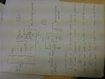
DSC_0049.JPG

pls find the schematics

- - - Updated - - -

Claus:

i think it is a diffrential amplifier only insted of gnd i biased the non inverting terminal with 2.5 volt reference.

Are there any wrong connections.

I am getting the desired output with the Differential amplifier avoiding level shifter stage.

Kindly advice if i am wrong so i can correct it..

DSC_0049.JPG
 

Hi,

If you want the first circuit to be a true difference amplifier, then:
Cut the line from non inverting input to 2.5V and connect a 100k instead.

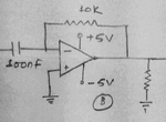
If you want the second circuit to be a true differentiator, then don't use the capacitor(shown in previous schematics) in the feedback path.

*****
My hint: keep it simple.
Now you have two opamps, one connected to gnd as lower supply rail, the other to -5V.
--> use a TL072, supplied with +/-5V.

Don't shift the signal by 2.5V DC. Instead of connecting the (new) 100k resistor to 2.5V connect it to GND.

Try this and show both opamp outputs.

Klaus
 
If you want the second circuit to be a true differentiator, then don't use the capacitor(shown in previous schematics) in the feedback path.

The second circuit is a "true" differentiator, but unfortunately, it's unstable with usual OPs. You need a small resistor with 100 nF capacitor (100 to several 100 ohms, depending on the OP bandwidth) or a parallel capacitor to the 10k feedback resistor to achieve stability. The compensation can be best designed in loop gain bode diagram.
 
Your latest schematic shows the opamp at the top as an inverting amplifier with a bias of +2.5V. It has its (+) input shorted to +2.5V so the (+) input has no 50Hz signal and this opamp is not a differential amplifier anymore.

Why are you differentiating the 50Hz sinewave? A differentiator passes high frequencies (there are not any high frequencies here) and reduces low frequencies. If it is a pure sinewave with no harmonics then it will simply be phase shifted and its level will be reduced.
 

@Audioguru:

I am making a ac interuption circuit where ac voltage can be interrupt for 5-10 ms
the ac changes are fast so i can capture the High dv/dt & accordingly give the sense to the control for the protections.
 

Why do you want to interrupt the electricity? One cycle of 50Hz is 20ms, half a cycle (which half, the positive half or the negative half?) is 10ms and 1/4 of a cycle is 5ms.

Dv/dt is the change in voltage divided by a change of time. Why do you want to capture dv/dt and to control what? Protections against what?

I think one of your schematics mentioned v_spike? Are there voltage spikes on your electricity that you want to measure? What causes the voltage spikes? Usually a MOV is used to stop voltage spikes if the current is not too high for a MOV. A MOV (metal oxide varistor) conducts when its voltage rating is exceeded, like a bi-directional zener diode. It does not need a control, it is automatic.
 

Hi,

The second circuit is a "true" differentiator,
I never used a capacitor in the feedback path when I built a differentiator...

Klaus
 

Why do you want to interrupt the electricity? One cycle of 50Hz is 20ms, half a cycle (which half, the positive half or the negative half?) is 10ms and 1/4 of a cycle is 5ms.

Dv/dt is the change in voltage divided by a change of time. Why do you want to capture dv/dt and to control what? Protections against what?

I think one of your schematics mentioned v_spike? Are there voltage spikes on your electricity that you want to measure? What causes the voltage spikes? Usually a MOV is used to stop voltage spikes if the current is not too high for a MOV. A MOV (metal oxide varistor) conducts when its voltage rating is exceeded, like a bi-directional zener diode. It does not need a control, it is automatic.

Guru.
you can think of Ac disapper for the short intervalsay for 5ms.
in that conditions if it come back to the normal conditions then the transformer needs Magnetising current. so i want to protect relays by giving protection. when next time ac appears it will follow the same routines that is thrush the Ntc & limit current & then i will switch to relay once transformer is magnetised purely.

Thanks
 

I never used a capacitor in the feedback path when I built a differentiator...
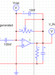
With "true differentiator", I was referring to the (unfortunately unstable) circuit sketched in post #12.

diff2.png

I presume you have been talking about the circuit from post #1

diff.png

As already mentioned by Audioguru, you should absolutely avoid the capacititive load at the OP output. Also obviously, the large capacitor in the feedback path cancels the differentiator action at relative low frequencies. But omitting it without other compensation means makes the circuit unstable.

An OP circuit can never implement an ideal frequency response because the loop gain needs to roll-off somehow. In case of the differentiator circuit, there must be a loop gain zero before crossing unity. A feedback capacitor (surely a smaller value than 10 nF) or a series resistor to the 100 nF differentiator capacitor are possible means.

Beside true differentiator stability issues, I agree with Audioguru that the purpose of the circuit is still mysterious.
 

Status
Not open for further replies.

Similar threads

Part and Inventory Search

Welcome to EDABoard.com

Sponsor

Back
Top