Continue to Site

Welcome to EDAboard.com

Welcome to our site! EDAboard.com is an international Electronics Discussion Forum focused on EDA software, circuits, schematics, books, theory, papers, asic, pld, 8051, DSP, Network, RF, Analog Design, PCB, Service Manuals... and a whole lot more! To participate you need to register. Registration is free. Click here to register now.

Why don't the best results of S21 and S11 occur in the same frequency?

Status
Not open for further replies.

bejing

Member level 2
Joined
Sep 7, 2015
Messages
42
Helped
0
Reputation
0
Reaction score
0
Trophy points
6
Activity points
330
Why best results of s21 and s11 don't occures in same frequency?

Hi dear friends,
I see this problem in some simulations of passive devices and transitions (more in ms line and stripline).
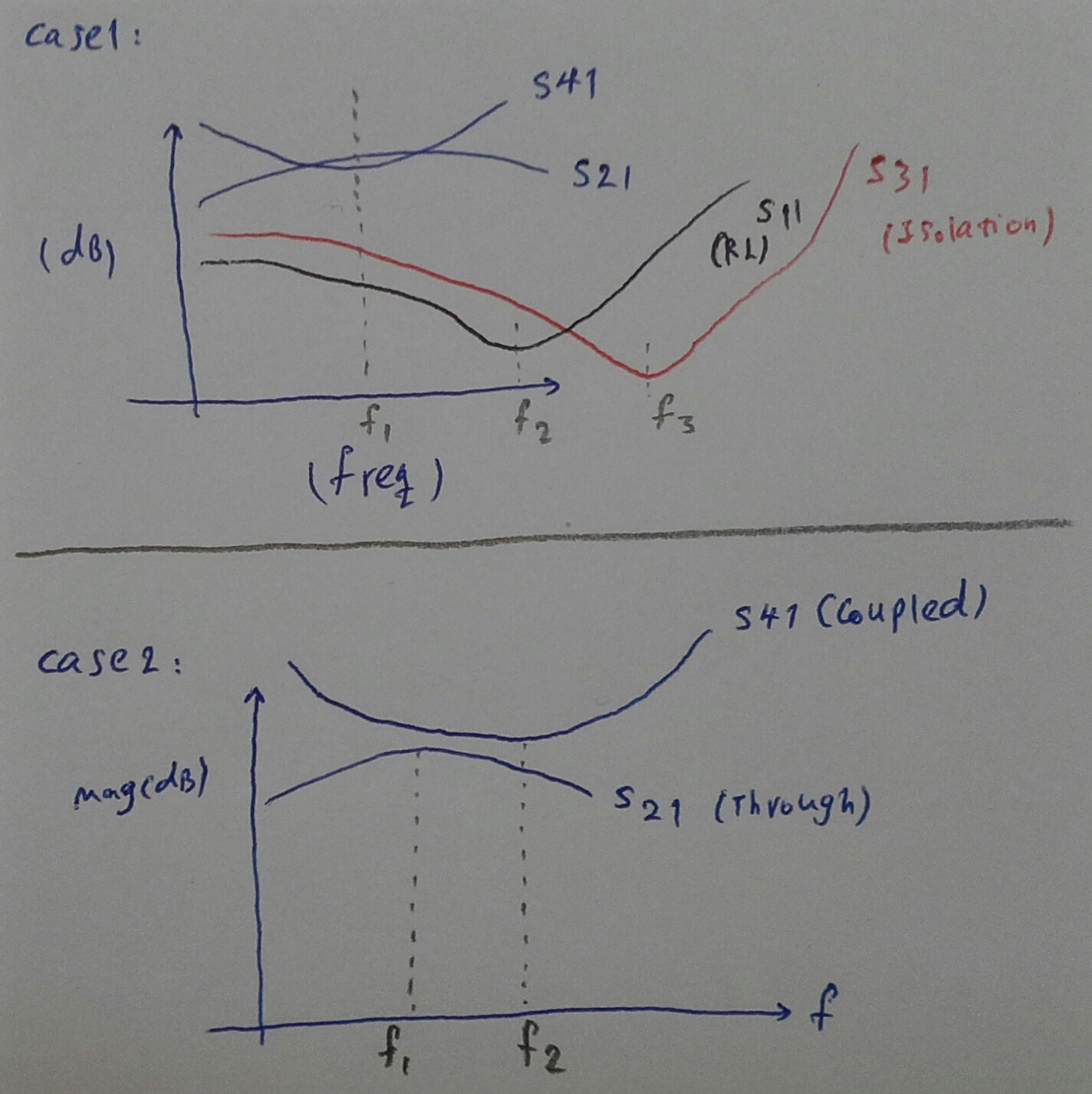
When im designing a coupler, the best results of return loss and isolation are not in the same frequency of the best results obtaining for insertion loss.
Also it may be occured for the insertion loss of through line and coupled line so the peak value and minimum value of these two graph are not in a same frequency.
Can anyone describe the reason of these phenomenon?
Thanks so very much.
 

Re: Why best results of s21 and s11 don't occures in same frequency?

It can happen if you test jig is not calibrated with the Network ANalyzer.
Poor quality cables and connectors can add phase shift and losses.
Always use semi-rigid coax for better results.

The s21 series insertion loss is related to the shunt return loss of both the input and the outputs, so the s11, s22 may have different Series and Parallel resonant frequencies, (SRF, PRF) with respect to the s21 when mismatch at either end. (i.e. not conjugate matched)

One can improve on SRF of chip caps by using them in vertical orientation instead of horizontal.
 
Last edited:
  • Like
Reactions: bejing

    bejing

    Points: 2
    Helpful Answer Positive Rating
Re: Why best results of s21 and s11 don't occures in same frequency?

Hi,


I notice that there are two definitions of insertion loss going around. The first is simply S21, while the less used one is |S21|^2 /(1-|S11|^2). Personally I always differentiate between S21 and insertion loss. Which one are you referring to?

Anyway, one point is that not all of the power is reflected or transmitted, some of it is dissipated in the circuit. This breaks the relationship between S21 and S11. If you look into absorptive filters, for example, you will see that there's hardly any relationship between S11 and S21.


regards,
Aaron
 
  • Like
Reactions: bejing

    bejing

    Points: 2
    Helpful Answer Positive Rating

    junhao

    Points: 2
    Helpful Answer Positive Rating
Re: Why best results of s21 and s11 don't occures in same frequency?

Thanks dear sunnyskyguy and dear aaron_do.
Let me show my problem on two graphs.
Case 1 and case 2 may be occured in a coupler.
I ask that is it possible to bring f1, f2 and f3 in same frequency or theoretically or physically it may not realizable?
Is it relative to even and odd mode impedances, inhomogenous media or something like this phenomena?
I am using stripline and microstrip.
 

Re: Why best results of s21 and s11 don't occures in same frequency?

Do you use real or ideal components in your simulation? Or is this the result of a EM-simulation of your couple?
 

Re: Why best results of s21 and s11 don't occures in same frequency?

These are from real coupled lines modeled in EM environment (ads layout).
 

Re: Why best results of s21 and s11 don't occures in same frequency?

Can you post a pic of your layout? As aaron_do wrote, the problem should be found in the layout of your coupler.
 

Re: Why best results of s21 and s11 don't occures in same frequency?

Hello johnjoe,
my problem is public.
I want to know the possible problems that may cause these nonsymmetrical responses.
 

Status
Not open for further replies.

Part and Inventory Search

Welcome to EDABoard.com

Sponsor

Back
Top