d123
Advanced Member level 5
Power transistor low "on" voltage
Hi,
I'm using the 2SB507 as a regulator bypass transistor, and have a small concern about the specific two I am testing the circuit with which I wanted to use:
A few months ago, the same type of transistor (perhaps even the same batch, they came in the same bag of 10) had a fully on voltage drop of 0.65 - 0.7V, and a guesstimated hFE of ~100.
Yesterday, having problems with the bypass resistor calculation and reality not coinciding, I checked the hFE of the two I am using and the "on" voltage. The "on" voltage is only ~0.32V for either of the two (the gains are ~200 and ~250 respectively).
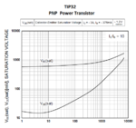
Is that normal for a transistor which in the datasheet only says for Vbe on saturation: max. 1.5V, but mentions no minimum, or could the transistors be damaged and not wise to use in a real circuit?
I must/may have used them for breadboarding at some point in the past, so may or may not have done something detrimental to them, but I doubt that, even if it is a possibility, and they both are working as per expected.
...Also, if it's okay to tag another question on here: Can I use 4 5V voltage regulators (3 x 7508, 1 x 73801 LDO) to separate four parts of the same circuit @ 9VDC supply voltage?
It's to power a CD4060, a 7135 ADC, a constant current source circuit, and lastly a CD4511 + 6 NPN + 5 x 7-segment displays - so I'd really like to keep each part of the circuit on it's own supply, but all connected on the same ground plane (best I can come up with for the ground problem).
If it helps, 2SB507 datasheet:
View attachment BJT PNP 2SB507.pdf
Thanks
Maybe I did something incorrect measuring, don't see how, but anyway: ...I measured the "on" voltage the same as the last time, using a resistor from +V in series with a trimpot to 0V as a voltage divider, and had the base at full supply voltage (from the trimpot wiper) then lowered it until the collector went from 0V (actually 3mV to 6mV) to 8.70V. 8.7V is what I get from the regulated DC 9V supply. I used a 100R in series with the 1K trim.
Last edited:
