Continue to Site

Welcome to EDAboard.com

Welcome to our site! EDAboard.com is an international Electronics Discussion Forum focused on EDA software, circuits, schematics, books, theory, papers, asic, pld, 8051, DSP, Network, RF, Analog Design, PCB, Service Manuals... and a whole lot more! To participate you need to register. Registration is free. Click here to register now.

Strange Gain and Phase waveforms

Status
Not open for further replies.

chaitanyab

Member level 3
Joined
Dec 8, 2009
Messages
67
Helped
3
Reputation
6
Reaction score
3
Trophy points
1,288
Location
Pune
Activity points
1,877
Hi,

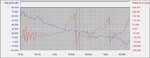
I am trying to measure the stability of Flyback converter, when I have inserted the frequency analyzer in the feedback loop using 20 ohm and isolation transformer in series with the feedback connection and performed the measurements, I found quite strange waveforms. The Gain is not becoming zero and phase waveform looks unusual.
Can anyone know what is wrong?
I am attaching the waveforms.

Thanks,
 

Attachments

  • Test1.jpg
    Test1.jpg
    47 KB · Views: 146

The phase plot ends at the +180 degree line, and resumes at -180 degrees. It is a 'wrap around'. It is a mathematically correct plot as far as that goes.

I can't say how many such wrap-arounds there should be on your graph, or whether all the phase values are correct.
 

Hello,
There is some problem there, because your open loop gain should be getting to zero well before 10Megahertz......your gain line should be crossing the zero line at most probably about 1-2KHz or so.
 

Hi Treez,

I am bit confused about the term Open loop gain, I had a close loop and have injected signal in the feedback path and the measurement was made keeping the loop still closed. Why would it be called as open loop response? and yes my problem is Gain not becoming Zero in KHz range.
 

Well, you “broke” open the feedback loop to put in your injection resistor, and then you injected, and you saw what your open loop gain is…it was open loop gain, because you had to break the feedback loop to get it.

The whole prospect of measuring a feedback loop by closing the loop and looking at the closed loop is a misnomer…I mean the whole point of feedback loop analysis is that you do it “before” you close the loop, (when the loop is open) so that you can see if it will go unstable or not when the loop is closed….so all of the feedback loop graphs that we look at to check for stability are “open loop” graphs.

Don’t forget the many systems that we look at in feedback analysis are so dangerous that closing the loop and getting instability may cause a huge explosion and kill us…so we always need to evaluate the loop open first, to see if it is ok to close it…

Yes your loop was closed when you measured it, but the open loop bit is still in there..so it can be measured…….and breaking the loop and shoving in the injection resistor allowed you to do that….remember the response of a closed loop is a math expression involving the open loop parameters as some of its parts.

As you know, it is no good saying that you’ve got “closed loop” measurements that tell you its ok to close the loop..because you’ve already done it……and in some cases, , may have unfortunately caused an enormous explosion.
 

As long as the injection shunt or resistor is low value the supply operates closed loop and you are measuring the closed loop response, you may have lots of noise due to low level signal injection - not uncommon - giving you garbage results, you need to restrict the injection range to 10Hz - 15kHz, use the biggest signal that will not upset the power supply (dependent on your injection point) and try and arrange all your cables etc to be coaxial and screened, and not to pick up too much RFI from the PSU under test - this may give you better results.

Another approach is to have a switchable (mosfet) load step say 50 - 75% and run this load as a square wave 50-75-50-75... switched by the fet, and run the freq from 10Hz - 15kHz, looking at the edge recovery on the o/p voltage will give you good insight as to the stability - you can use the overshoot and number of cycles to steady state to tell you the gain and phase margins from this approach also...

Good luck...!

- - - Updated - - -

Also a lot of power supplies are only marginally stable at no load due to the lack of damping on the output filters at no load, so the operating point of the converter (no load, 2% load, 10% load, 33%, 50%, 75% 90% 100%) will alter the power stage loop and hence the overall loop, the feedback loop has to take account of this - hence a lot of feedback control is slow and over-damped compared to what it could be if it just ran at 50-100% load only...
 

Open loop gain includes all the DC and AC gain blocks around the loop and is the best way to characterize the loop from DC to beyond gain crossover. Closed loop gain plot may not show conditional stabilty issues among other key aspects to stability.

When you put in an injection resistor like this, and inject, it is the measurement of "open loop" gain.
For a reference , see page 91 of book “power supply design volume 1: control by Dr Raymond Ridley.
This point is directly discussed there.
The loop is only electronically opened at the injection frequency, and kept closed and in regulation at all other frequencies.
 
Last edited by a moderator:

How do you do closed loop gain then? given that the injection resistor is low ohms - the loop is still closed - as the o/p is regulated, putting in small perturbations on one side of the injection resistor and seeing what happens on the other manages to include all the stages of the power supply (as you state above), power and control - hence you are seeing the response of the complete loop.

Open loop certainly shows you some of the gate drive control (PWM, pk current mode, etc) and the power stage, but does not include the error amp that closes the control loop, you have to disconnect the o/p of the error amp to do open loop measurements - hence open loop, and put it back in to do closed loop - hence closed loop measurement.

Open loop does not require an injection resistor, closed loop does, closed loop is a powerful tool which when used over the complete load range will tell you how stable your power supply is.

Open loop has to have a load that matches the operating point of the converter to keep the o/p volts (or current) to a safe level, and the exciting signal is usually added to the Vref (or I ref as desired), sometimes the error amp is made a unity gain follower and biased via a small trimmer to get it to the correct operating point (no Vsense or I sense connected), then the small external signal is used to modulate the Vref (or I ref) causing modulation of the o/p. By seeing the delay and amplitude of the o/p compared to the input perturbation you can see how the power stage (and some of the control) either follows closely the demand signal (low freq) or, as you go higher in freq, lags with lower amplitude...
90 degree power lag and 90 degree control lag at a frequency with overall gain >1 = oscillation.

Only the Closed loop measurement will show you this....!
 

As far as I know, the said "frequency analyzer" is determining closed loop gain by applying Middlebrook's method.

There are certain prerequisites regarding circuit impedances to get a correct result, due to lack of meaningful information we can't check if they are fulfilled in your measurement.

I believe the requirements and limitations are well described in the instrument's manual and related application notes.
 

As Dr Ridley says..
The loop is only electronically opened at the injection frequency, and kept closed and in regulation at all other frequencies.
When you put in an injection resistor like this, and inject, it is definitely the measurement of "open loop" gain. See pages 90 onwards of book referenced in post #7
 

If that is so - how do you measure closed loop gain...? I think you need to read again...
 
  • Like
Reactions: treez

    T

    Points: 2
    Helpful Answer Positive Rating
I can assure that I have read Dr Ridley's book clearly (referred to in post #7) , pages 90 - 96, and the measurement that we are speaking about in the top post is "open loop gain".
I believe once one has the open loop gain, one can calculate the closed loop gain from that.
The page is attached here, as you know, Dr Ridley is the foremost person on gain of SMPS, his articles are always intuitive and have a clarity not seen in any other writer.
The points raised in post#8 are explained from pg 90 onwards in Ridleys book. It is certainly open loop gain.
 

Attachments

  • Dr Ridley on open loop gain.pdf
    681.9 KB · Views: 161
Last edited by a moderator:

So, can you tell me how you measure closed loop gain on a power supply?

- - - Updated - - -

I've read that too, its not 100% correct, especially for small injection resistors and small injected signals...
 
  • Like
Reactions: treez

    T

    Points: 2
    Helpful Answer Positive Rating
.. but really its needed to read the whole chapter, and it explains that out. (concerning small signals etc, and noise etc, the AP300 literature also explains it, Dr ridley is 100% right on this) I am not sure how much of a book its legal to post on a forum, does anyone know? (I think its 10% of the book?)
Measuring Closed loop gain, you can calculate it from the measured open loop gain and some other parameters I believe.
However, as you know, the graph of interest to PSU designer is the open loop one, from which you get the gain and phase margin.

- - - Updated - - -

Here is another article from Dr Ridley, it concerns transient response which we spoke of in post#6....There are problems with getting stability analysis out of transient response as you know.
Also, as we all know, the open loop graph is not everything....it doesnt concern times when the error amplifier may be railed after eg a transient or at startup etc.
 

Attachments

  • _17 Transient Response _STEP response n stability.pdf
    1.2 MB · Views: 147
Last edited by a moderator:

The page linked in post #12 shows a voltage injection setup, but doesn't actually explain the method. You better read Middlebrook's article "Measurement of loop gain in feedback systems" for an exact explanation. I'm not allowed to post the copyrighted paper here.

It suggests that the discussed setup uses voltage injection and measurement of the loop gain by voltage ratio. It works if Rsource << Rload for the branch where you open the loop.
 
  • Like
Reactions: treez

    T

    Points: 2
    Helpful Answer Positive Rating
@ Treez, I spoke to Dr. Ridley, he confirms it is open loop only, even with hi-Z current fed injection to the injection resistor,
 

The page linked in post #12 shows a voltage injection setup, but doesn't actually explain the method. You better read Middlebrook's article "Measurement of loop gain in feedback systems"
Thanks ill take a look, but the rest of Ridleys book explains it.
Thanks for speaking to Dr Ridley, I suppose the hanging question now for all of us, is, how to get the closed loop gain, and why one as a PSU designer, would want it, when one already has measured the open loop gain.
 

Well I have asked for clarification, as open loop gain has to be defined, what parts of the converter does it include.?

If you have the open loop gain/phase of the power stage + modulator (e.g. PWM, vary freq, etc) then you can easily design the Vea to give overall gain/phase that will be stable (at worst case load) .

Load switching will then confirm stability...of the closed loop system
 

I suppose the hanging question now for all of us, is, how to get the closed loop gain, and why one as a PSU designer, would want it, when one already has measured the open loop gain.
Which closed loop gain? The set point transfer function? It isn't of much interest for a fixed set point. Load response (= complex output impedance) and response to input voltage variations are probably more important. But they all depend on open loop gain.

I would suggest to return to the original question. The measurement method discussion was brought up because people doubted if and how it works at all. We can review the theory, but we don't know if was applied correctly in the discussed measurement.

Consequently we need more information about the setup. The shown unity bandwidth of > 10 MHz suggests elementary faults.
 

Status
Not open for further replies.

Similar threads

Part and Inventory Search

Welcome to EDABoard.com

Sponsor

Back
Top