Electro nS
Full Member level 6
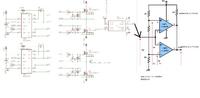
i have been working sometime with servo control (position and speed) of brushed dc motor in the KW range . Traditionally i am using locked antiphase (50% duty =zero speed) as i read it is better for controlling the motor . i am sensing motor current in both directions to operate in 4 quadrant .
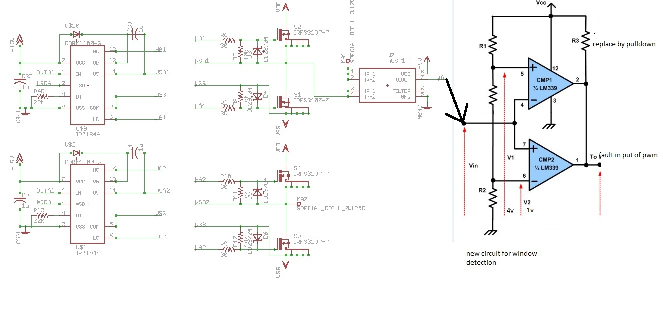
Now i want to implement the current limiting cycle by cycle in hardware instead of software for convenience ... the uC i am using has PWM fault input that i can use to shutdown PWM for one cycle in case of over-current ( in the positive or negative direction (2.5v is the zero current) ) the problem is that it puts the both pwm signal to either HIGH or LOW state , however my zero should be at 50% duty instead , i cannot find a solution for this other than replacing locked anti-phase with sign magnitude ...
please give me ur opinion , what is the best method for servo control , is there any method for driving h bridge that i donot know about ? is there any solution for the problem and if you have any comments on the opamp circuit
")