Continue to Site

Welcome to EDAboard.com

Welcome to our site! EDAboard.com is an international Electronics Discussion Forum focused on EDA software, circuits, schematics, books, theory, papers, asic, pld, 8051, DSP, Network, RF, Analog Design, PCB, Service Manuals... and a whole lot more! To participate you need to register. Registration is free. Click here to register now.

[General] Connect DC motor to microcontroller

Status
Not open for further replies.

omerysmi

Member level 5
Joined
Oct 10, 2014
Messages
91
Helped
0
Reputation
0
Reaction score
0
Trophy points
6
Activity points
1,128
If i connect dc motor to my arduino in this way:
learn_arduino_schematic.jpg

How could i know what is the current that flows through the motor when the transistor is on? there is no any resistor between the 5v to the motor..
 

the current is limited by what the motor can draw.
but if you really require , you can measure or monitor in a scope.

the transistor simply operate as switch.

other than that , is it working in your test?
 

the current is limited by what the motor can draw.
but if you really require , you can measure or monitor in a scope.

the transistor simply operate as switch.

other than that , is it working in your test?

but it could damage the motor no?
 

1. you would apply a current sensing rasister middle of GND and where GND connect to transister.
2. Use a extrnal CT.

- - - Updated - - -

you can test by mutimeter also.
 

but it could damage the motor no?

it will not damage the motor.
think the transistor as switch , and you are switching it ON like a conventional switch.
the DC motor is connected to the dc supply directly , if you recall.
 

put a low value shunt between emmiter and ground instead of directly grounding it then measure voltage using meter (or adc on micro) at emmiter shunt junction

you can convert measured voltage (will be very low) into current by using ohms low
 

hello,


With a shunt , wich must be a very low value compare to the internal resitance of motor, you
will get a very low level .. any mV , so must use an AOP to amplifie mV -> Volts..
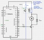
Maybe another solution with a photocoupler ..
will decrease voltage across motor near 0,6V maxi( + Delta Volt across your Tr Q1)
The phototransitor can amplifie the signal across R collector.
and you obtain a reverse signal wich feed an anlog input

Imesure_photocoupler.jpg

maybe to add a low value resistor across the diode of phototransisto can improve the linearity.

or you can add a hall effect sensor **broken link removed**
 
Last edited:

What is written on the motor? If it is in fact a 5V motor, it is meant to be connected directly to 5V DC.

And as far as connecting a shunt resistor to measure current is concerned, it's not of any use for a motor of this size (assuming it to be a 5V motor). The current will be extremely small. You will need very high quality and expensive equipment, or an expensive instrumentation amplifier to see such a tiny current, which will most probably be even less if the motor is on no load, which I suppose it would be. Believe me, I've tried. You have to stall the motor to see the tiniest change on a DSO.

In conclusion, no need to think of the current if you apply voltage lesser than or equal to the rated value.
 

True chinuhark
So long as
1. The motor is operated at rated or lower voltage
2. Current consumed by motor is within the capacity of supply
The transistor is just a switch, consider other issues if not functioning as per expectations.
 

You could always try hall effect based current sensors...I remember seeing them a few years ago and noticing that they themselves do not draw much power.
 

The best way is use a other power source for motor... Because ripple in mcu may be cause reset...

I think about this!!!
 

Hello!

Just a remark. You mention a bipolar transistor. That's indeed a solution, but I think it's not
the right one. Among the reasons:
1. You will loose power due to the transistor which has a CE voltage even if saturated.
2. You cannot spin in both direcions.
3. You cannot brake.

You should use an integrated circuit (full bridge). And a recent one, not a L193 which is bipolar
if I remember right.

For small devices you can use for example DRV8848 (from Texas) which has 2 full bridges
and allows you to drive either 2 DC or one stepper. But depending on the current (this one is
for 1A max), you will have to choose other devices.

Dora.
 

Status
Not open for further replies.

Part and Inventory Search

Welcome to EDABoard.com

Sponsor

Back
Top