Mjollnir
Newbie level 2
Hi everybody,
I met a problem in PLL design.
Actually design has finished, the problem found in verification.
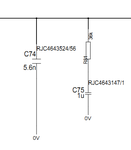
TI PLL chip 4816B is used, and follow is the external 2nd order LPF.

For VCXO, we have several vendor to select. All of the VCXOs works well except one. The phenomena is the PLL will unlock with only 30ppm offset at reference. But it's about 100+ppm on others.
We measured the phase error between input reference and PLL output. It's very small at beginning, but will change and be stable if offset added at referernce. For example, the beginning is assuming 0ppm, and when offset added it will be 5ppm at not change back to 0ppm. The phase error will be back to 0ppm if other vendor's VCXO used.
The input impedance is measured on board, not single component. The problem one is about 100kohm, while others is about 10Mohm.
My question is:
1. Can we say the problem is caused by the input impedance mismatch?
2. What influence will be if low input impedance VCXO used?
3. From phenomena, it seems PLL can't catch up changes at reference, is it about delay? What influence will be when delay added in feedback loop?
Thanks.
Br.
I met a problem in PLL design.
Actually design has finished, the problem found in verification.
TI PLL chip 4816B is used, and follow is the external 2nd order LPF.

For VCXO, we have several vendor to select. All of the VCXOs works well except one. The phenomena is the PLL will unlock with only 30ppm offset at reference. But it's about 100+ppm on others.
We measured the phase error between input reference and PLL output. It's very small at beginning, but will change and be stable if offset added at referernce. For example, the beginning is assuming 0ppm, and when offset added it will be 5ppm at not change back to 0ppm. The phase error will be back to 0ppm if other vendor's VCXO used.
The input impedance is measured on board, not single component. The problem one is about 100kohm, while others is about 10Mohm.
My question is:
1. Can we say the problem is caused by the input impedance mismatch?
2. What influence will be if low input impedance VCXO used?
3. From phenomena, it seems PLL can't catch up changes at reference, is it about delay? What influence will be when delay added in feedback loop?
Thanks.
Br.