micropar
Member level 1
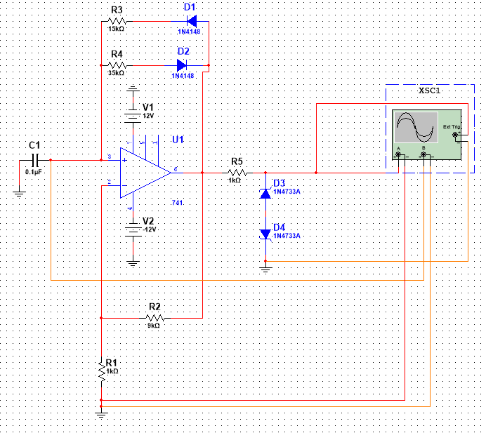
Problem Statement: Design astable mulitvibrator using op-amp IC 741 for frequency 1 KHz.and peak to peak voltage of 10V and duty cycle less than 50%. Plot its output response and compare with theoretical response.
Attached circuit diagram and file of multisim. What to do to see output on virtual DSO of Multisim?
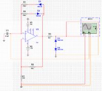
<a title="Sq_Wave_Gen_with_741_on_Multisim.png" href="http://obrazki.elektroda.pl/4493658000_1444567474.png"><img src="http://obrazki.elektroda.pl/4493658000_1444567474_thumb.jpg" alt="Sq_Wave_Gen_with_741_on_Multisim.png" /></a>
https://obrazki.elektroda.pl/4493658000_1444567474.png
Attached circuit diagram and file of multisim. What to do to see output on virtual DSO of Multisim?
<a title="Sq_Wave_Gen_with_741_on_Multisim.png" href="http://obrazki.elektroda.pl/4493658000_1444567474.png"><img src="http://obrazki.elektroda.pl/4493658000_1444567474_thumb.jpg" alt="Sq_Wave_Gen_with_741_on_Multisim.png" /></a>
https://obrazki.elektroda.pl/4493658000_1444567474.png