Continue to Site

Welcome to EDAboard.com

Welcome to our site! EDAboard.com is an international Electronics Discussion Forum focused on EDA software, circuits, schematics, books, theory, papers, asic, pld, 8051, DSP, Network, RF, Analog Design, PCB, Service Manuals... and a whole lot more! To participate you need to register. Registration is free. Click here to register now.

[SOLVED] What is the problem in this 4-bit LCD Code?

Status
Not open for further replies.

xpress_embedo

Advanced Member level 4
Joined
Jul 5, 2011
Messages
1,154
Helped
161
Reputation
396
Reaction score
189
Trophy points
1,353
Location
India
Activity points
10,591
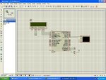
I am using PIC18F4550, with the following Schematic
Schematic.JPG

My Code is as follow:

Code C - [expand]
1
2
3
4
5
6
7
8
9
10
11
12
13
14
15
16
17
18
19
20
21
22
23
24
25
26
27
28
29
30
31
32
33
34
35
36
37
38
39
40
41
42
43
44
45
46
47
48
49
50
51
52
53
54
55
56
57
58
59
60
61
62
63
64
65
66
67
68
69
70
71
72
73
74
75
76
77
78
79
80
#include <xc.h>
#include "UART.h"
#include "LCD.h"
 
// CONFIG1L
#pragma config PLLDIV = 5       // PLL Prescaler Selection bits (Divide by 5 (20 MHz oscillator input))
#pragma config CPUDIV = OSC1_PLL2// System Clock Postscaler Selection bits ([Primary Oscillator Src: /1][96 MHz PLL Src: /2])
#pragma config USBDIV = 2       // USB Clock Selection bit (used in Full-Speed USB mode only; UCFG:FSEN = 1) (USB clock source comes from the 96 MHz PLL divided by 2)
 
// CONFIG1H
#pragma config FOSC = HSPLL_HS  // Oscillator Selection bits (HS oscillator, PLL enabled (HSPLL))
#pragma config FCMEN = OFF      // Fail-Safe Clock Monitor Enable bit (Fail-Safe Clock Monitor disabled)
#pragma config IESO = OFF       // Internal/External Oscillator Switchover bit (Oscillator Switchover mode disabled)
 
// CONFIG2L
#pragma config PWRT = OFF       // Power-up Timer Enable bit (PWRT disabled)
#pragma config BOR = ON         // Brown-out Reset Enable bits (Brown-out Reset enabled in hardware only (SBOREN is disabled))
#pragma config BORV = 3         // Brown-out Reset Voltage bits (Minimum setting)
#pragma config VREGEN = ON      // USB Voltage Regulator Enable bit (USB voltage regulator enabled)
 
// CONFIG2H
#pragma config WDT = OFF        // Watchdog Timer Enable bit (WDT disabled (control is placed on the SWDTEN bit))
#pragma config WDTPS = 32768    // Watchdog Timer Postscale Select bits (1:32768)
 
// CONFIG3H
#pragma config CCP2MX = ON      // CCP2 MUX bit (CCP2 input/output is multiplexed with RC1)
#pragma config PBADEN = OFF     // PORTB A/D Enable bit (PORTB<4:0> pins are configured as digital I/O on Reset)
#pragma config LPT1OSC = OFF    // Low-Power Timer 1 Oscillator Enable bit (Timer1 configured for higher power operation)
#pragma config MCLRE = ON       // MCLR Pin Enable bit (MCLR pin enabled; RE3 input pin disabled)
 
// CONFIG4L
#pragma config STVREN = ON      // Stack Full/Underflow Reset Enable bit (Stack full/underflow will cause Reset)
#pragma config LVP = OFF        // Single-Supply ICSP Enable bit (Single-Supply ICSP disabled)
#pragma config ICPRT = OFF      // Dedicated In-Circuit Debug/Programming Port (ICPORT) Enable bit (ICPORT disabled)
#pragma config XINST = OFF      // Extended Instruction Set Enable bit (Instruction set extension and Indexed Addressing mode disabled (Legacy mode))
 
// CONFIG5L
#pragma config CP0 = OFF        // Code Protection bit (Block 0 (000800-001FFFh) is not code-protected)
#pragma config CP1 = OFF        // Code Protection bit (Block 1 (002000-003FFFh) is not code-protected)
#pragma config CP2 = OFF        // Code Protection bit (Block 2 (004000-005FFFh) is not code-protected)
#pragma config CP3 = OFF        // Code Protection bit (Block 3 (006000-007FFFh) is not code-protected)
 
// CONFIG5H
#pragma config CPB = OFF        // Boot Block Code Protection bit (Boot block (000000-0007FFh) is not code-protected)
#pragma config CPD = OFF        // Data EEPROM Code Protection bit (Data EEPROM is not code-protected)
 
// CONFIG6L
#pragma config WRT0 = OFF       // Write Protection bit (Block 0 (000800-001FFFh) is not write-protected)
#pragma config WRT1 = OFF       // Write Protection bit (Block 1 (002000-003FFFh) is not write-protected)
#pragma config WRT2 = OFF       // Write Protection bit (Block 2 (004000-005FFFh) is not write-protected)
#pragma config WRT3 = OFF       // Write Protection bit (Block 3 (006000-007FFFh) is not write-protected)
 
// CONFIG6H
#pragma config WRTC = OFF       // Configuration Register Write Protection bit (Configuration registers (300000-3000FFh) are not write-protected)
#pragma config WRTB = OFF       // Boot Block Write Protection bit (Boot block (000000-0007FFh) is not write-protected)
#pragma config WRTD = OFF       // Data EEPROM Write Protection bit (Data EEPROM is not write-protected)
 
// CONFIG7L
#pragma config EBTR0 = OFF      // Table Read Protection bit (Block 0 (000800-001FFFh) is not protected from table reads executed in other blocks)
#pragma config EBTR1 = OFF      // Table Read Protection bit (Block 1 (002000-003FFFh) is not protected from table reads executed in other blocks)
#pragma config EBTR2 = OFF      // Table Read Protection bit (Block 2 (004000-005FFFh) is not protected from table reads executed in other blocks)
#pragma config EBTR3 = OFF      // Table Read Protection bit (Block 3 (006000-007FFFh) is not protected from table reads executed in other blocks)
 
// CONFIG7H
#pragma config EBTRB = OFF      // Boot Block Table Read Protection bit (Boot block (000000-0007FFh) is not protected from table reads executed in other blocks)
 
void main()
{
  unsigned char msg[] = "Keyboard Test Program!\r\n";
  unsigned char receive = 0;
  ADCON1 = 0x0F;
  Lcd4_Init();
  UART_Init();
  UART_Write_Text(msg);
  Lcd4_Write('A');  
  {
    receive = UART_Read();
    UART_Write(receive);
  }
}


Lcd 4 Bit Library

Code C - [expand]
1
2
3
4
5
6
7
8
9
10
11
12
13
14
15
16
17
18
19
20
21
22
23
24
25
26
27
28
29
30
31
32
33
34
35
36
37
38
39
40
41
42
43
44
45
46
47
48
49
50
51
52
53
54
55
56
57
58
59
60
61
62
63
64
65
66
67
68
69
70
71
72
73
74
75
76
77
78
79
#include "LCD.h"
 
void Lcd4_Cmd(unsigned char value)
{
  LCD_RS = 0;
  LCD_DATA = (value>>4) & 0x0F;
  LCD_EN = 1;
  __delay_ms(10);
  LCD_EN = 0;
  LCD_DATA = (value & 0x0F);
  LCD_EN = 1;
  __delay_ms(10);
  LCD_EN = 0;
  __delay_ms(1);
}
void Lcd4_Write(unsigned char value)
{
  LCD_RS = 1;
  LCD_DATA = (value>>4) & 0x0F;
  LCD_EN = 1;
  __delay_ms(10);
  LCD_EN = 0;
  LCD_DATA = (value & 0x0F);
  LCD_EN = 1;
  __delay_ms(10);
  LCD_EN = 0;
  __delay_ms(1);
}
 
void Lcd4_Write_Text(unsigned char msg[])
{
  while(*msg)
  {
    Lcd4_Write(*msg);
    msg++;
  }
}
 
void Lcd4_Init(void)
{
  __delay_ms(10);
  __delay_ms(10);
  TRISA = 0x00;
  TRISEbits.TRISE0 = 0;
  TRISEbits.TRISE1 = 0;
  TRISEbits.TRISE2 = 0;
 
  LCD_RS = 0;       //Command Register
  LCD_RW = 0;
  LCD_EN = 0;
 
  LCD_DATA = 0x03;
 
  LCD_EN = 1;  
  __delay_ms(10);
  LCD_EN = 0;
  __delay_ms(10);
 
  LCD_EN = 1;
  __delay_ms(10);
  LCD_EN = 0;
  __delay_ms(10);
 
  LCD_EN = 1;
  __delay_ms(10);
  LCD_EN = 0;
  __delay_ms(10);
 
  LCD_DATA = 0x02;  // Four bit mode
  LCD_EN = 1;
  __delay_ms(10);
  LCD_EN = 0;
  __delay_ms(10);   
 
  Lcd4_Cmd(0x28);
  Lcd4_Cmd(0x0C);
  Lcd4_Cmd(0x01);
  Lcd4_Cmd(0x06);
}


But nothing comes on the display.
I am also attaching the full MPLAB X project, written in version 3.10 and XC8 version 1.35
 

Attachments

  • Keypad.zip
    218.7 KB · Views: 61

Is this strictly a simulation or have you implemented your design in physical hardware?

After only glancing at your code, two issues come to mind:

1. You got a code block define within main(), however there is no Superloop, i.e., while(1) associated with it.

Code:
void main()
{
  unsigned char msg[] = "Keyboard Test Program!\r\n";
  unsigned char receive = 0;
  ADCON1 = 0x0F;
  Lcd4_Init();
  UART_Init();
  UART_Write_Text(msg);
  Lcd4_Write('A');  
  [COLOR="#FF0000"]{[/COLOR]
    receive = UART_Read();
    UART_Write(receive);
  [COLOR="#FF0000"]}[/COLOR]
}

Therefore the code is only executed once before code execution exits main() to parts unknown.

2. If you've implemented the code in physical hardware, LCDs of this type typically need a minimum of 30ms to 50ms to fully initialize internally, before they properly accept your code's initialization commands. As your code exists at present only approximately 20ms is provided, which may not be sufficient.

Code:
void Lcd4_Init(void)
{
[COLOR="#FF0000"]  __delay_ms(10);
  __delay_ms(10);[/COLOR]
  TRISA = 0x00;
  TRISEbits.TRISE0 = 0;
  TRISEbits.TRISE1 = 0;
  TRISEbits.TRISE2 = 0;
 
  LCD_RS = 0;       //Command Register
  LCD_RW = 0;
  LCD_EN = 0;
 
  LCD_DATA = 0x03;
 
  LCD_EN = 1;  
  __delay_ms(10);
  LCD_EN = 0;
  __delay_ms(10);
 
  LCD_EN = 1;
  __delay_ms(10);
  LCD_EN = 0;
  __delay_ms(10);
 
  LCD_EN = 1;
  __delay_ms(10);
  LCD_EN = 0;
  __delay_ms(10);
 
  LCD_DATA = 0x02;  // Four bit mode
  LCD_EN = 1;
  __delay_ms(10);
  LCD_EN = 0;
  __delay_ms(10);   
 
  Lcd4_Cmd(0x28);
  Lcd4_Cmd(0x0C);
  Lcd4_Cmd(0x01);
  Lcd4_Cmd(0x06);
}

I've downloaded your project files and will examine them further when time permits.

BigDog
 
I'm not familiar with Proteus, but shouldn't you provide a polarsation voltage to the pin of display which adjusts the LCD contrast ?
 
In the simulation, you have wired the LCD and PIC in a wrong way.
wire
RA0 -> LCD.D4
RA1 -> LCD.D5
RA2 -> LCD.D6
RA3 -> LCD.D7

Also to be sure, ground LCD.D0 to LCD.D3 to ground.
 
In the simulation, you have wired the LCD and PIC in a wrong way.
wire
RA0 -> LCD.D4
RA1 -> LCD.D5
RA2 -> LCD.D6
RA3 -> LCD.D7

Also to be sure, ground LCD.D0 to LCD.D3 to ground.

Thanks duresh
It was a connection mistake from me.
After changing its working.
I don't how i did that stupid mistake.

A0 -> LCD.D4
RA1 -> LCD.D5
RA2 -> LCD.D6
RA3 -> LCD.D7
 

Status
Not open for further replies.

Similar threads

Part and Inventory Search

Welcome to EDABoard.com

Sponsor

Back
Top