Continue to Site

Welcome to EDAboard.com

Welcome to our site! EDAboard.com is an international Electronics Discussion Forum focused on EDA software, circuits, schematics, books, theory, papers, asic, pld, 8051, DSP, Network, RF, Analog Design, PCB, Service Manuals... and a whole lot more! To participate you need to register. Registration is free. Click here to register now.

RMS power with DC offset

Status
Not open for further replies.

100k

Member level 1
Joined
Jun 16, 2012
Messages
37
Helped
1
Reputation
2
Reaction score
1
Trophy points
1,288
Activity points
1,607
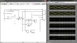
I am simulating a sinusoidal source (v(t) = 10sin50t +1 V) connected to R-C circuit (1 - 1j) ohms. Capture.JPG

The DC component should not contribute towards the current because of capacitor but would increase the voltage across the load. By theoretical analysis, the RMS voltage across the R-C circuit should be sqrt(51) and RMS current should be 10/sqrt(2)/sqrt(2) =5 A.

So, the RMS power should be 5*sqrt(51) =35.7 VA.

But Simulink simulation showed different values for RMS current and power (RMS power = Vrms*Irms= ~50).
The voltage was varying between -9 to 11 V as expected and current did not have offset as expected. But why the RMS value of the power is different from theoretical calculations?
What is possibly wrong?
 

Hi,

but would increase the voltage across the load.
What do you suggest to be the load? The R alone? Or the RC combination?

the RMS voltage across the R-C circuit should be sqrt(51)
I suspect this is not correct. But I will check this and come back with the answer.

RMS current should be 10/sqrt(2)/sqrt(2) =5 A.
This is definitely not correct. Check on this.

So, the RMS power should be 5*sqrt(51) =35.7 VA.
There is no "RMS power", what you calculate is called "apparent power".
Also here you should say if you mean R or RC.

(RMS power = Vrms*Irms= ~50).
So either Vrms or Irms or both are incorrect. Did you check this?

What is possibly wrong?
My hint: What is the RMS voltage of 10sin50t?

Klaus
 

Hi,

I suspect this is not correct. But I will check this and come back with the answer.
I checked on this. The right value is indeed sqrt (51). So you were right with this.

Klaus, IRMS=5A is the only right answer
Not my day today. I must admit this is true, too. I didn'see why there is two times sqrt (2).
Now I see it: 1 unit real part plus 1 unit imaginary part....
Sorry.

Klaus
 

Guys!!
I think RMS voltage is sqrt(51) V and RMS current should be Vrms/|Z|=10/sqrt(2)V/sqrt(2)V because capacitor is blocking the current.

I think the RMS power should be Prsm = Vrms*Irms =sqrt(51)V * 10/sqrt(2)/sqrt(2)A = 35.7VA, the power delivered by the source which is the power consumed by the capacitor and resistor combined.

Why Simulink showed a different result?

I used RMS of current and RMS of voltage at fundamental frequency and multiplied them.
Vrms was correct (around 7V) but RMS of current was not 5A and simulation showed that current was varying from 10A to -10A. It is confusing!!
I used fixed step and discrete solver in simulation configuration.

What is wrong, simulation or some theory?
 

Guys!!
I think RMS voltage is sqrt(51) V and RMS current should be Vrms/|Z|=10/sqrt(2)V/sqrt(2)V because capacitor is blocking the current.

This thinking is right.

I think the RMS power should be Prsm = Vrms*Irms =sqrt(51)V * 10/sqrt(2)/sqrt(2)A = 35.7VA, the power delivered by the source which is the power consumed by the capacitor and resistor combined.

But this is totally wrong.

RMS mean "Root Mean Square" what is the operation applied to the signal.
What you insist on calling rms power is the Active Power and Vrms*Irms is the Apparent Power (Pactive=Papparent only with resistive loads).

In linear systems you may evaluate the Power (active) by the sum of powers corresponding to each of the harmonic components.

Then, I of dc component is 0 and I of 1st (and unique) harmonic is 5A, but cosφ = 1/√2

so Power = VRMS_1st_H*IRMS_1st_H*cosφ = (10/√2)*5*(1/√2) = 25W

Or, easier, the total power will be equal to the power dissipated by R.

so Power = I^2RMS*R = 5^2*1 = 25W

Why Simulink showed a different result?

I used RMS of current and RMS of voltage at fundamental frequency and multiplied them.
Vrms was correct (around 7V) but RMS of current was not 5A and simulation showed that current was varying from 10A to -10A. It is confusing!!
I used fixed step and discrete solver in simulation configuration.

I think you did wrong the model in Simulink.

What is wrong, simulation or some theory?

You, who did not understood the theory.
 

Hi, Eduardo!!

Capture.JPGCapture1.JPG

From this simulation setup please let me know where I am doing it wrong? <R =1 ohm, C= 0.02 F, RMS calculated ar 20/(2*pi) Hz, V= 1+10 sin 50t V>

I am interested in all the power supplied by the source (apparent power). Should it be Vrms^2/|Z| = 51/sqrt(2) =36.06VA or Vrms*Irms = sqrt(51)*5=35.7 VA. I think 35.7 because capacitor does not allow DC current through it.
Why does Simulink shows an entirely different result?
Is it because the current is computed by neglecting the capacitor?

Can we use Power = VRMS_1st_H*IRMS_1st_H*cosφ to compute the real power?
I think the phasor diagram of the voltage would be shifted by a unit towards the right side on real axis because of DC source. The phase difference, in this case should it be the vector sum or simply the phase difference between the rotating quantities?
 

Irms is in fact Vrms/|Z| (single frequency or frequency independent |Z| presumed), in so far both expressions should give the same VA (apparent power) value.
 

Irms is in fact Vrms/|Z| (single frequency or frequency independent |Z| presumed), in so far both expressions should give the same VA (apparent power) value.

Buddy!! it is just shown that they are different.

Please explain the simulation results. I want to know what does it mean and why it is different from the opinions of each of us.
 

....
From this simulation setup please let me know where I am doing it wrong? <R =1 ohm, C= 0.02 F, RMS calculated ar 20/(2*pi) Hz, V= 1+10 sin 50t V>

I am not a user of Simulink and I haven't got installed Matlab to check, but I see a current meter with output shorted. I(t) never reach 10V as is plotted.
(*)

I am interested in all the power supplied by the source (apparent power).

"all the power supplied by the source" is the Active Power.

Should it be Vrms^2/|Z| = 51/sqrt(2) =36.06VA or Vrms*Irms = sqrt(51)*5=35.7 VA. I think 35.7 because capacitor does not allow DC current through it.

You have learned two formulas: Irms=Vrms/|Z| and P=Vrms*Irms and wants to apply here somehow.
Forget please, these formulas are valid only when all sources are sinusoidals and the same frequency. And in this case they aren't.

If you do not understand what this means, please read about circuits at polyharmonic regime instead of insisting with your misconceptions.

Why does Simulink shows an entirely different result?
Is it because the current is computed by neglecting the capacitor?

See (*)

Can we use Power = VRMS_1st_H*IRMS_1st_H*cosf to compute the real power?

Yes, but remember, in this formula cosf corresponds to the phase shift of the 1st harmonics of current and voltage.
Beware, because the definition of power factor in polyharmonic regime is Pactive/Papparent


I think the phasor diagram of the voltage would be shifted by a unit towards the right side on real axis because of DC source. The phase difference, in this case should it be the vector sum or simply the phase difference between the rotating quantities?

You can't draw a standard phasor diagram in polyharmonic regime because the instantaneous phase is time dependant.

- - - Updated - - -


Furthermore, it does not seem simulated at 50rad/s = 7.9577Hz
 

As said, apparent power = Vrms^2/|Z| can be only used for single frequency or frequency independent |Z|.

You have AC + DC superposition (not single frequency), |Zac| = √2, |Zdc| = ∞.
 

I see that the error in your simulation is the source frequency.

I feel that your goal is calculate the power delivered by the source in anyway, simply use the power of a dipole definition , which is the average of the product V(t)*I(t).

The image is the simulation at f=50rad/s
I add a block who calculates the active power (25W)
 

Attachments

  • RC_mongui.jpg
    RC_mongui.jpg
    163.8 KB · Views: 83

Status
Not open for further replies.

Part and Inventory Search

Welcome to EDABoard.com

Sponsor

Back
Top