Continue to Site

Welcome to EDAboard.com

Welcome to our site! EDAboard.com is an international Electronics Discussion Forum focused on EDA software, circuits, schematics, books, theory, papers, asic, pld, 8051, DSP, Network, RF, Analog Design, PCB, Service Manuals... and a whole lot more! To participate you need to register. Registration is free. Click here to register now.

Horrible humming sound in Transformer

Status
Not open for further replies.

swapan

Full Member level 4
Joined
Feb 20, 2009
Messages
199
Helped
27
Reputation
54
Reaction score
24
Trophy points
1,298
Location
Kolkata
Activity points
2,806
Hi Friends,

In a Home UPS available in India I have noticed that charging the battery (150 – 200 AH, Lead Acid) is done by using the same transformer tapped at nearly 130V. AC mains (generally 220 V) is given to that tap controlled by SCR/TRIAC, fired at required angle so that charging current is maintained at certain level. I have undertaken to make such a charging system using PIC MCU. When testing, it is seen that the project works well except a problem at a particular point. If the firing angle is set near zero crossing point ( say at 10 degree and 190 degree of a cycle), a horrible humming is produced in the transformer and sometimes the AC mains fuse is blown without any charging current. But beyond that point the circuit works smoothly.

I guess that due to lagging of current behind voltage and firing of thyristor this humming is produced. I request you to offer your valued comment please.
 

the harmonics at that angle , makes the core vibrarion and produce a humming sound.
 

Hi Friends,

In a Home UPS available in India I have noticed that charging the battery (150 – 200 AH, Lead Acid) is done by using the same transformer tapped at nearly 130V. AC mains (generally 220 V) is given to that tap controlled by SCR/TRIAC, fired at required angle so that charging current is maintained at certain level. I have undertaken to make such a charging system using PIC MCU. When testing, it is seen that the project works well except a problem at a particular point. If the firing angle is set near zero crossing point ( say at 10 degree and 190 degree of a cycle), a horrible humming is produced in the transformer and sometimes the AC mains fuse is blown without any charging current. But beyond that point the circuit works smoothly.

I guess that due to lagging of current behind voltage and firing of thyristor this humming is produced. I request you to offer your valued comment please.

Not knowing your circuit I cannot comment on electrical events. Hum is generated in a laminated core when sheets are loose. As you use a SCR, harmonics of the AC pulse current are easier to hear.
Either avoid the states close to zero-crossing point, or use hard wax to seal the core.
Some core materials are magnetostrictive and will generate a sound . There is no cure but to enclose the device or relocate it.
 

Not knowing your circuit I cannot comment on electrical events.

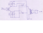
Sorry to be so late in posting the schematic. Please see the circuit diagram. Please go through it and suggest the needful.

SCR_CHG.png
 

A special proble with small phase angles can be that triggering might become unreliable, or an unaccurate zero crossing detector results in occasional overflow to 180 degree half waves. Both cases can result in DC voltage across the transformer, core saturation and blown fuses.
 

If you trigger at a very low input voltage then you will get a very small ON current which means the SCR will not latch. So the output will be off, like wise there not be enough voltage to drive the gate ON hard. It would help if the gate drive had its own power source, one variable removed!.
Frank
 

Firing at 10 degrees you are applying 98% of 220 volts to the primary of a 130 volt transformer!!
 

an unaccurate zero crossing detector results in occasional overflow to 180 degree half waves

It seems to be the most likely scenario.
In addition, instead of triggering the thyristors with a pulse having the same frequency that the wave cycle, a pulse train would be more reliable.
 

FvM said:
A special proble with small phase angles can be that triggering might become unreliable, or an unaccurate zero crossing detector results in occasional overflow to 180 degree half waves.

I have examined zero crossing pulse as well as the triggering pulse using CRO and observed that they are very steady and clear. I could not get your observation of 'overflow to 180 degree half waves' please.

Code:
Firing at 10 degrees you are applying 98% of 220 volts to the primary of a 130 volt transformer!!

Yes. Mains AC is controlled so that 130V/12V transformer gets correct input throughout mains range from 220V - 130V. The more is mains the more is firing angle and vise-versa.

Code:
a pulse train would be more reliable.

I shall certainly make experiment of your valued suggestion and apprise the outcome.
 

If your firing is out of phase with the mains applied to the Tx, then there will be a net DC in the Tx, which will cause the humming and fuse blowing...
 

I have examined zero crossing pulse as well as the triggering pulse using CRO and observed that they are very steady and clear. I could not get your observation of 'overflow to 180 degree half waves'

I understand that the trigger pulses are regular. Did you also observe the tarnsformer input voltage?

"Overflow to 180°" can happen with a badly designed phase control. I mentioned it because it could explain blowing fuses. Good f it's not the case.

Correct triggering means the humming is just normal operation with your transformer. There's nothing we can do about it.

I presume you know that a fast fuse can be blown due to transformer inrush current. It won't happen in steady state or when increasing the input voltage continuously. If it happens however at low phase angles, I suspect there's a problem with the triggering circuit, though.

Operating an inductive load or an unloaded transformer with triacs can cause triac self-triggering after switch-off if no suitable RC snubbers are used. Another possible explanation for blown fuses.
 

If it happens however at low phase angles, I suspect there's a problem with the triggering circuit, though.

Yes. Malfunction happens at low phase angles.

Actually the moment AC mains is turned on, firing TRIAC is set to extreme high angles of phase (near 180 degree and 360 degree). Gradually the firing angle is lowered resulting in soft rise of charging current. As soon as charging current reaches preset value, the firing angle is settled there. If for any reason charging current varies - the firing angle is varied accordingly.

I have tested the unit using varied input voltage using Variac. As I go on decreasing input voltage, the triggering pulse go on moving towards lower angle and stops to a point that I have set to avoid half wave overflow where, due to very low input, there is no charging current. Upto a certain point (say 45 degree of phase angle) everything is ok. After that the transformer starts vibrating vigorously making horrible humming.

In actual circuit, snubber is there but I missed it to sketch.
 

Well, could you take some scope waveforms? You got us playing a guessing game here.
Please include, if the scope has such a funcion, the RMS value. Also measure that the phase angle in the positive and negative semicyles is identical
 

Well, could you take some scope waveforms? You got us playing a guessing game here.
Please include, if the scope has such a funcion, the RMS value. Also measure that the phase angle in the positive and negative semicyles is identical


Sorry to place such a problem. I have an old analogue Scope that has no provision to measure the parameters you asked.

Please comment if there is any problem under the condition when current of positive half cycle has not reached to zero and the TRIAC/SCR has been fired for negative half cycle (when negative half cycle has already attained some magnitude). I am guessing under such condition the problem is creating. I am not sure, that's why expert comment is requested please.
 

Sorry to place such a problem. I have an old analogue Scope that has no provision to measure the parameters you asked.

Do you have an RMS multimeter?
Can you take a good photo with of the analog scope screen? Well focused, please.
 

Are you using full wave or half wave zero crossing signals ? ...if using half wave zero cross and from that calculating next zero cross then this may not work as this may introduce a unbalanced SCR firing angles.
Next , in these types of SCR firing schemes you can not utilize the full wave`s energy as you need to keep firing points decently far from actual zero crossings (this is due to many reasons one among them that at near actual zero crossings there may not be much energy in the wave to meet the lathing/holding current demands of thyristors/SCRs).
so rule of thumb formula should be to fire at some maximum and minimum times after zero cross signal detected by the micro controller ...
Hint : Always fire at the most after 9 milliseconds AND not less then 4 milliseconds of the zero cross signal detected by the micro controller .
 

Are you using full wave or half wave zero crossing signals ?.

I am using full wave zero crossing.

Code:
Hint : Always fire at the most after 9 milliseconds AND not less then 4 milliseconds of the zero cross signal detected by the micro controller .

Yes, I have noticed this in such gadgets of renowned manufacturers. The triggering pulse is constrained to a certain limit towards lower phase angle. As I tried to further lower the firing angle, this problem occurred. This has prompted me to post this thread. So, is it the reason of the problem - that required latching current is not there?
 

Status
Not open for further replies.

Similar threads

Part and Inventory Search

Welcome to EDABoard.com

Sponsor

Back
Top