Continue to Site

Welcome to EDAboard.com

Welcome to our site! EDAboard.com is an international Electronics Discussion Forum focused on EDA software, circuits, schematics, books, theory, papers, asic, pld, 8051, DSP, Network, RF, Analog Design, PCB, Service Manuals... and a whole lot more! To participate you need to register. Registration is free. Click here to register now.

Clock frequency to voltage converter

Status
Not open for further replies.

amsdesign

Member level 3
Joined
Aug 26, 2015
Messages
67
Helped
0
Reputation
0
Reaction score
0
Trophy points
6
Activity points
550
Hello everyone,


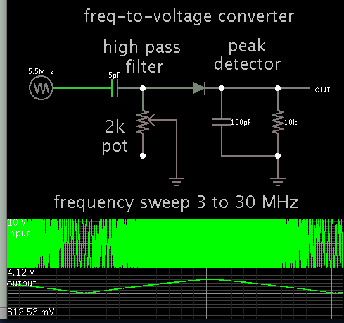
I have a clock signal that varies from 10Mhz- 100Mhz and I need to generate a voltage proportional to the frequency as it varies in step size of 50kHz.

Is there any way to accomplish this? Would a simple RC High pass filter solve the problem? :(


Edit: I'm not looking for any IC. I want a circuit to perform the job
 
Last edited:

This simulation portrays how an RC high pass filter might be used as a F-to-V converter.


Your frequency range will probably require a special fast diode.

You must choose component values so that your source signal is able to drive the circuit. Notice if your input resistance is very high, then it will change the RC time constant, which will alter the shape of your rolloff curve.

Thank you BradtheRad.
What exactly is the function of the peak detector in the circuit?
As in, why is it needed? The HPF produced a voltage proportional to the input frequency anyways right?
 

Thank you BradtheRad.
What exactly is the function of the peak detector in the circuit?
As in, why is it needed? The HPF produced a voltage proportional to the input frequency anyways right?

I assumed you wanted DC output, that is the purpose of the peak detector.

You may omit it if you want AC output.
 

Hi,

A clock signal is square wave...Therefore the RC may introduce some unlinearity.

What about a VCO with phase comparator feedback, like a PLL? Use the VCO input signal. It is as linear as the VCO's V-f linearity.

Another approach could be a counter with constant time gating/zeroing. Give the counter values to a DAC.
Clear counter, count the clock pulses for exactely 10us, send the counter value to a 10 bit DAC.

Klaus

Hi Klaus, if I were to use a PLL to generate the DC voltage wouldn't I face this problem : The PLL tries to lock to the input frequency so the DC voltage fed to the VCO will keep decreasing over time. I would like a constant voltage (DC) for a particular frequency.

- - - Updated - - -

I assumed you wanted DC output, that is the purpose of the peak detector.

You may omit it if you want AC output.

I tried simulating your circuit for a clock signal t 100Mhz.

Unfortunately the output DC rises from 0 and settles only at 10u which is a long settling time. Anyway to make it settle much faster? I'm talking in 100's of nano secs
 

Hi,

The PLL tries to lock to the input frequency so the DC voltage fed to the VCO will keep decreasing over time. I would like a constant voltage (DC) for a particular frequency.

Why do you think it is decreasing? VCO input voltage should be constant for a constant frequency. Ideally it is proportional to frequency.
Low voltage low frequency, high voltage high frequency, constant voltage colnstant frequency.
For sure this is only true when locked. Unlocked you will see garbage.

Klaus
 

I tried simulating your circuit for a clock signal t 100Mhz.

Unfortunately the output DC rises from 0 and settles only at 10u which is a long settling time. Anyway to make it settle much faster? I'm talking in 100's of nano secs

If your clock signal is pulsed DC, then apparently the simple RC high-pass filter does not work so well (as Klaus indicates in post #5). You lose linear response. Furthermore the simulation reveals a mode which behaves in reverse, that is, low-frequency input causing a greater voltage at the output.

The voltage/current swings can be enhanced by using a very small capacitor, 1 or 2 pF.

To get the type of output you want, will require rearranging of the circuit.

- - - Updated - - -

Is your duty cycle at 10 MHz different from duty cycle at 100 MHz? If so then you might take advantage of that in some way, to exaggerate the difference somehow, and apply it to a capacitor, or RC arrangement, or DCR arrangement, etc.
 

Status
Not open for further replies.

Part and Inventory Search

Welcome to EDABoard.com

Sponsor

Back
Top