Continue to Site

Welcome to EDAboard.com

Welcome to our site! EDAboard.com is an international Electronics Discussion Forum focused on EDA software, circuits, schematics, books, theory, papers, asic, pld, 8051, DSP, Network, RF, Analog Design, PCB, Service Manuals... and a whole lot more! To participate you need to register. Registration is free. Click here to register now.

Parasitic inductance of battery cable causing MOSFET ringing

Status
Not open for further replies.

mrinalmani

Advanced Member level 1
Joined
Oct 7, 2011
Messages
463
Helped
60
Reputation
121
Reaction score
58
Trophy points
1,318
Location
Delhi, India
Activity points
5,285
Hi!
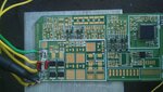
I have a hard switched MOSFET bridge connected to a 12V 48Ah battery through 30cm long cables.
There is a single 1uf film capacitor on the PCB connected across the power rails.
The cables will have self inductance that calculates to 300nH - 500nH approximately.

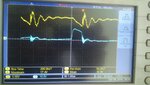
The combination of capacitor and stray cable inductance should give a ringing frequency (during dead band) of 225KHz however the measured frequency is 2MHz.
This implies that the stray inductance is only around 10nH!

Am I missing something or is this a typical value of stray inductance?
Also what is the approx value of on board filer capacitors for a 12V 1000VA high frequency inverter?
Doesn't the dead band during switching cause ringing issues?

Thanks
 

If there was no dead band your bridge would be taking 1000/12 ~ 80 A continuosly. During the dead band (2microsecs long with .1 microsecs rise/fall time), it takes not current. So its like having a -80A pulse sitting on a DC level of +80A. This would cause ringing, Vr = di (80)/dt(10^-7) X L, = 8 X 10^8 X L or .8V per nano H.
Any ESR in the cap will drop volts, could be a SRF problem, put in a second identical cap, if it a SRF problem the ring frequency will stay the same, if its a lead problem the the frequency will fall by 30%.
As an RF engineer I am constantly amazed by the thin leads and marginal designs of the new medium power low frequency transmitters ( SMPSs), if it was in a RF transmitter there would be 5 capacitors returned to a 3 mm ali chassis.
Frank
 

Most likely you are seeing a different resonance at 2 MHz.

A standard "twisted pair" power cable has about 0.5 µH/m. Because inductance is a function of
ln(center distance/wire diameter), you can't go much below this value unless you are using multiple wires.

1 µF is a very small filter capacitor, I would expect at least several mF for a 12V inverter.
 

Thanks for the reply

I put an identical capacitor and tested it again., this time with 80% dead band. (1u conduction and 4us dead)
The frequency INCREASED by nearly 30%! However the magnitude of overshoot decreased. This is absolutely ironic. The frequency should have decreased.
Perhaps two capacitors in parallel have lower ESL. But then what about the added capacitance? And also where has the inductance of the cable disappeared?

Without the capacitor, the frequency is nearly 24MHz.


I had placed only one capacitor to magnify the ringing effect and measure the cable inductance.

See the attached photos. Blue colour is the gate signal. Yellow is the rail voltage 12V.
 

Attachments

  • DSC_0004.jpg
    DSC_0004.jpg
    1 MB · Views: 118
  • DSC_0006.jpg
    DSC_0006.jpg
    1,017.1 KB · Views: 117

Hi,

The cables will have self inductance that calculates to 300nH - 500nH approximately.

Did you do the calculation as a single wire?
If both power supply wires are in proximity to each other this reduces the single inductance significantely.

Klaus
 

No... not for single wire. This is for two parallel wires.
For single it comes out to be more.
 

A "single wire" has no defined inductance unless you specify the return path. Inductance is a property of the complete current loop.

Double wire inductance according to text books is

detail.png

Gives the said 0.5 µH/m for typical power cables.

- - - Updated - - -

The inductance of the green/yellow wire pair in post #4 is rather 1 to 1.5 µH/m.
 

The test battery is old. The voltage drop due to internal resistance probably bleaches the effect of cable inductance. Will post again after testing with a new 150Ah 12V lead acid battery...
 

Where are you taking your CRO earth from? The yellow race shows the 12V dropping during the conduction period. I wonder if the increased ringing frequency is due to the two sets of leads now to your decoupling capacitor also you have removed some of the series inductance but not all off it. The leads to your decoupling capacitors look too long for the fast rise time. You could try putting a fast square wave across your capacitor with long leads and measure the voltage with a CRO. if the leads and capacitor are good at this frequency you will get zero volts, if they are above the SRF, you will get a sine wave.
Frank
 

Status
Not open for further replies.

Similar threads

Part and Inventory Search

Welcome to EDABoard.com

Sponsor

Back
Top