Continue to Site

Welcome to EDAboard.com

Welcome to our site! EDAboard.com is an international Electronics Discussion Forum focused on EDA software, circuits, schematics, books, theory, papers, asic, pld, 8051, DSP, Network, RF, Analog Design, PCB, Service Manuals... and a whole lot more! To participate you need to register. Registration is free. Click here to register now.

[SOLVED] Resistivity meter design.

Status
Not open for further replies.

moeedmughal

Junior Member level 2
Joined
Oct 1, 2015
Messages
21
Helped
0
Reputation
0
Reaction score
0
Trophy points
1
Location
United Kingdom
Activity points
196
Hello all,

I want to design a resistivity meter to measure resistivity of rock and sediment cores. I have gone through Wenner array (four electrodes) method which is an established technique. What are the other options to measure electric resistivity ? Any help regarding implementation of Wenner array or development of resistivity meter will highly be appreciated. Thank you in advance.
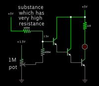
 

A simple method is a darlington arrangement of transistors. If each transistor has 100 gain, then this provides total 100 x 100 x 100 gain.

You'll need very high gain to measure resistance of rocks. The bias current goes through the rock. Whatever there is, it is amplified.


Where my schematic has an led, you'll probably put a micro-ammeter.

The resistor values are a guess, several hundred megohms.

If you need more gain, then add a fourth or fifth transistor. Also try increasing your supply voltage.

It's possible you won't need any potentiometer adjustment through the high-ohm resistor. You can install a switch inline with it, just in case.
 
Hi,

For your application you need to measure the current for a given voltage.
Then you can calculate R = U / I. (Ohm's law).

But for your application you may need to calculate "volume resistivity"
Then you need to calculate the mechanical dimensions like A (electrode area) and d (electrode distance).

pv = R * A / d [Ohm * cm]

Klaus
 
Hi Klaus,

Thank you to answer my post. Yes, i want to calculate the volume resistivity of rock samples which have irregular shapes/surfaces. Are you refering to wenner array meathod for voltage and current measurements or it could be a simple two electrode meathod (apply a potential difference and measure current passed through the sample) ?

By "A" you mean area of electrode in contact with sample only? Electrodes i will be using are cylidrical pins.

Moeed M.
 

Hi,

Thank you to reply. Can i use current sensing circuit as a micro-ammeter ? I have seen a suface resistivity meter with measurment options at 10V and 100V. I was wondering if a DC-DC converter can step-up input supply (e.g. 12V to 100v) ?

What do you mean by "1.5V" at the base of first transistor ?
Can i directly ground 400M resistor if calibration is not required ?
If calibration is required, then how potmeter connected to "+1.5V" will effect bais current ?

Moeed M.
 

Hi,

i don´tknow about wenner array.

***

electrode area:
My idea is an electrode with it´s whole area conducted with the sample. Mabe with conductive foam or conductive rubber pressed on the sample.

My given formula is the standard formula to calculate volume resistivity.

Klaus
 
Hi,

Thank you to reply. Can i use current sensing circuit as a micro-ammeter ? I have seen a suface resistivity meter with measurment options at 10V and 100V. I was wondering if a DC-DC converter can step-up input supply (e.g. 12V to 100v) ?

A boost converter is suitable. High voltage will make it easier for you to get a reading.

What do you mean by "1.5V" at the base of first transistor ?
Can i directly ground 400M resistor if calibration is not required ?
If calibration is required, then how potmeter connected to "+1.5V" will effect bais current ?

Moeed M.

1.5V indicates that a very low voltage will be sufficient to turn on the transistors.

The 400 megohm indicates a very high resistance. You need this because you are measuring a very high resistance (rock). Therefore you must avoid introducing a low impedance in the measuring circuit. In other words, the bias current needs to be miniscule.

I guessed that 400 megohm is sufficient, but I really do not know. It is up to you to experiment, to apply a range of bias current, at different voltages, so you can find a proper operating range for the transistors.

There is another issue not mentioned. Your setup can easily detect 50/60 cycle hum, due to the high impedance of your measuring leads. This can cause a false reading on your meter.

You must take precautions so that hum does not get at your measuring leads. Possibly use shielded cable. Possibly go to a place where there are no electrical wires, so that you can take readings in a noise-free surroundings.
 
Rocks are like a mixture of weak resistance and capacitance.
They make great insulators unless moist with contamination ( clay) becuase water has a dielectric constant 60x greater than air. Since all insulators are capacitors between any two conducting points, there is a risk of charging current on capacitance giving a lfase reading unless stable, so a slow varying AC voltage is often used which also prevents oxidation and galvanic response errors ( battery effect) of long term or high voltage DC on wet sediment, less on dry cores.

THe Wenner Array is basicall same as Kelvin Bridge method to avoid fringe current density giving false readings so the voltage readings are kept away from the source current probes. The gap depends on the resistance and capacitance. It can be mm for perfect conductors and xx meters for lossy/ capacitive earth to earth readings with deep probes.

I would consider a low frequency Square wave current source and measure the response step and triangle wave to determine Rs and Cp as a vector impedance.

Another method is to use a RLC meter which using very low current doesn't need a 4 terminal method as much. These measure R up to 20 GigaOhms and C as low as 1pF for $200 or so at various frequencies as well as Dissipation Factor, Series and parallel resistance and capacitance simultaneously.
 
You need AC excitation, as DC will polarize the electrodes and throw off the measurement. The frequency should be high enough that any polarization phenomena don't build up, but not so high that capacitance has an effect. I don't have any real numbers, but a few 100 Hz to a couple of kHz should be fine.

The upside is that you can now use synchronous rectification, getting rid of noise and off-set.
 
Hi SunnySkyguy,

Thank you to reply my query. I would like to go for slow varying AC voltage but unfortunately I do not have any experience with AC circuit designs. Can you guide me about low frequency square wave current source ? Will it be a constant current source ? What would be the easiest way to design an AC current source ?

As i remember, in wenner array distance between all electrodes is same for thesimplicity of calulation. I was thinking of four electrodes (pins) at equal distance in one line. The outer two for current source and the inner two for voltage measurement. Is their any other option to implement wenner array ?

RLC meter will not do the job, as i want to develop a stand alone resistivity meter.

Cheers !

Moeed M.
 

Hi BradtheRad,

Thanks again for a very detail reply. I have implemented it and tested it for upto several Gohms. I will test it for several hundered Gohms in next step. I will analyse the setup for any hum once i measure resistance in the required range. Hopfully, it will get sorted by sheilding cable.

In my setup i am using probes instead of electrodes and fix resistors (in Gohm range) instead of rock samples.

Cheers !

Moeed M.

- - - Updated - - -

Hi ydtech,

Thank you to reply. I agree with "AC excitation" idea instead of DC, but i have no idea how to proceed further. Why you mentioned synchronous rectification ?

Cheers !

Moeed M.
 

Also known as lock-in or chopper amplification. In effect, you amplify the signal with an AC amplifier, and then use the excitation signal to open/close a rectifying amplifier. This gets rid of off-set effects, and also works as a very narrow band filter, eliminating non-correlated hum and noise. Do a search on the net, there are enough circuit examples to give you some idea.
 
Hi SunnySkyguy,

Thanks again for your response. I want to implement your idea to supply low freq. square wave (AC) to rock sample. Things are getting better with resistivity meter. I don’t understand this bit "I would consider a low frequency Square wave current source and measure the response step and triangle wave to determine Rs and Cp as a vector impedance ".

What do you mean by response step and triangle wave?
What is Rs and Cp ?

Kindly explain, if possible.

Thanks a lot.

Moeed M.
 

Status
Not open for further replies.

Similar threads

Part and Inventory Search

Welcome to EDABoard.com

Sponsor

Back
Top