Continue to Site

Welcome to EDAboard.com

Welcome to our site! EDAboard.com is an international Electronics Discussion Forum focused on EDA software, circuits, schematics, books, theory, papers, asic, pld, 8051, DSP, Network, RF, Analog Design, PCB, Service Manuals... and a whole lot more! To participate you need to register. Registration is free. Click here to register now.

Suggestions for LED dimming circuit

Status
Not open for further replies.

Eight

Member level 2
Joined
Mar 8, 2013
Messages
53
Helped
1
Reputation
2
Reaction score
1
Trophy points
1,288
Activity points
2,084
Hello,

I'm working on a project (theoretical stage right now) and I need some suggestions. I plan to use 6 LED chains of different colors - that's multiple 5mm high brightness LED's wired serially in a single chain (all LED's in a given chain are the same color). Normally they draw about 20mA of current when fully lit, but the voltage needed to drive a chain is going to rise since multiple LED's are wired together. Anyway, I'd like to build a mechanism to digitally dim these chains independently of each other and I was wondering what's the recommended way to do so. I'll be using a 5VDC microcontroller to do the dimming logic.

One option I was thinking about is using a PWM driver, if I use a simple resistor (leds + resistors = bad idea???) on each chain to match the PSU voltage (24VDC). However I cannot find any 6-channel IC's that can supply a high enough voltage to drive the chains. I found this IC though: **broken link removed** In addition to this IC I'll probably have to use something like a MOSFET on each channel to drive the higher voltage chains. Thing is I have no experience with mosfets, and seeing that the PWM driver operates on 97KHz I'm not sure whether this is going to be a problem or not. I'll likely need a high frequency switching MOSFET so can anyone please recommend me which one to use?

The other idea is to use a constant-current driver that can digitally adjust the current flowing through the LED's. Again I'm clueless what to use here.

Thanks in advance for any suggestions.
 

hi,
How many LED's in each chain.?
Different coloured LED's have different forward voltage drops.

PWM would be the way to go for controlled dimming.
E
 

Hey,

There should be 5 or 6 per chain. I am aware that different led colors have different voltage drops, that's why I originally wanted to use per-channel resistors to match the voltage drop to that of the PSU (24V) so that the current flowing at 100% PWM duty cycle will be a continuous 20mA. Well maybe a bit less for certain channels because I also want to match the brightness i.e. I don't want the green one to be too bright.

Anyway, the LED voltage drops are here: https://www.oksolar.com/led/led_color_chart.htm
 

hi,
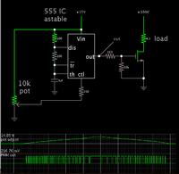
To keep the cost down I would use a 555 timer as a PWM generator for each chain.
For only 20mA per LED chain, from a 24Vdc source, a BJT or a 2N7000 MOSFET would be suitable.

The frame frequency of the 555 PWM generator could be selected for each LED colour chain.

Lots of simple circuits on the web.

https://www.google.com/search?q=555++pwm+led+driver+circuit&ie=utf-8&oe=utf-8
 

In a similar thread I posted how to match intensity Iv , angle and current with the brightest possible options from Digikey in 5mm. Since green was 8 Cd (8000mcd) vs Blue 3Cd it would only require 3/8 of 20mA = 7.5mA approx.

Always choose the series drop voltage with V+ tolerance in mind. If accurate or <1%, Most efficient is when V drop resistor < 1 LED drop. However Vf for Red Yellow are (2V) ~ 65% of Blue, Green, White ( 3~3.5)

Use PWM >=1kHz if possible to avoid peripheral eye movement flicker

- - - Updated - - -

If you decide to use RGB and want to synth any colour, care in nmD selection is required.

Other methods include RGBY or RRGBB or RGBW or RGBWY due to colour efficacy per pixel or diffuser panel and desired effects.
 

esp1: I'm not sure I understand your suggestion. How can I change the PWM duty cycle of a 555 circuit with a microcontroller? The IC I posted earlier does so via the I²C protocol.
SunnySkyguy: Hey, thanks. That will come handy. Also I'm not using RGBYWP led colors - guess which color the charactes refer to, they're all different. :)
 

A 555 timer IC can easily be made to change the duty cycle, according what voltage you apply at the adjustment pin.


You could control several 555's this way, with one adjustment. It might be by making the right arrangement of resistive dividers. Or something else.
 

BradtheRad: Forgive me, but I seem to be missing the point here. Can you please elaborate your solution? How can I change the adjustment pin voltage with a microcontroller? I would need some sort of DAC for that, but in this case I might as well just supply the DAC voltage directly to the LED's instead. No need for PWM when I have an option to adjust voltage directly, riiiiiight?

Regards!
 

BradtheRad: Forgive me, but I seem to be missing the point here. Can you please elaborate your solution? How can I change the adjustment pin voltage with a microcontroller? I would need some sort of DAC for that, but in this case I might as well just supply the DAC voltage directly to the LED's instead. No need for PWM when I have an option to adjust voltage directly, riiiiiight?

I'm sorry, I did not understand whether you want to dim/brighten all chains together simultaneously with one adjustment, or dim/brighten each led chain independent of other chains.

I guess it depends on how many jobs your microcontroller is able to do, and whether it can supply the required voltage, and required amperage.

I have no direct experience with microcontrollers, but I understand they have several output pins (On/Off). You may find it is possible to program it to pwm 6 mosfets independently. Each output pin would go high and low many times per second.

Example, all outputs go high simultaneously. Then the program pulls each output low after a designated duty cycle.

If you find you need middlemen devices, then it is convenient to implement analog settings through each one. So in that sense you're correct about needing to send a DAC voltage from the output pins. A different voltage to each middleman device.

The middleman devices might be sample-and-hold circuits. The output could adjust the duty cycle coming from a 555 timer IC, in the same manner shown in my post #8.

I cannot say which method requires more effort, compared to which method needs fewer parts, etc.
 

However I cannot find any 6-channel IC's that can supply a high enough voltage to drive the chains

If you found one with open collector or open drain drivers , you don't need high voltage as the LED Anode goes to high voltage and when you drive the Cathode string, the difference voltage should be <<<15% V+ . With FETs these days at Vgs=1V and Vds=6Vmax, that is plenty to drive any string up to 100V from the cathode side with Nch . using 3.3V logic.

If using fast PWM , and recovery time is slow, a simple R divider will provide pullup to +20% V+ to guarantee LED's off , for example without pulling all the way up to 24V or even 100+V

- - - Updated - - -

Maybe this will work for you
https://www.intersil.com/en/products/audiovideo/display-ics/led-backlight-drivers/ISL97636A.html

But it is better if you define all your inputs and controls/ effects, then outputs and supply range.
 

Status
Not open for further replies.

Similar threads

Part and Inventory Search

Welcome to EDABoard.com

Sponsor

Back
Top