Continue to Site

Welcome to EDAboard.com

Welcome to our site! EDAboard.com is an international Electronics Discussion Forum focused on EDA software, circuits, schematics, books, theory, papers, asic, pld, 8051, DSP, Network, RF, Analog Design, PCB, Service Manuals... and a whole lot more! To participate you need to register. Registration is free. Click here to register now.

Very Low Voltage on DIY square wave inverter

Status
Not open for further replies.

Rhizudin

Newbie level 4
Joined
Jun 26, 2013
Messages
7
Helped
0
Reputation
0
Reaction score
0
Trophy points
1,281
Activity points
1,343
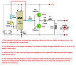
I try to build my own inverter based on circuit on the internet below :
opsi 2 (1).jpg
But when I measure the transformer output it just read about 50V. I use 12 V dr accu for power source.
This is my board and transformer.
DSC_0451_1280x960_800x600.jpgDSC_0452_1280x960_800x600.jpg
I also try to replace the transistor using 2N3055 and MJ2955. But nothing changed, it still about 50V at the output.
When I measure the frequency it has 50Hz after L1.
I have stuck for several weeks. Can someone help me what to do to solve this problem?
 

With 15Vdc and and 13.5Vpp square wave with a source impedance of around 1~2Ohm into a transformer with a voltage turns ratio of 1:2, you might expect 27Vpp output loaded
What were you expecting 220Vac? fuggedaboudit. not with this tiny circuit.
 

Sorry SunnySkyguy, i am new to electronic. But I just follow a tutorial on the internet that they said it work well. So, if this not possible, how should the circuit be?
 

50 HZ is the period of the wave form, it can be "ON" for any fraction of this, but for power conversion its best to be about 50%. The frequency is not all that critical, say 40 - 200 HZ would be close enough, unless you are driving an electric clock !
Frank
 

Sorry SunnySkyguy, i am new to electronic. But I just follow a tutorial on the internet that they said it work well. So, if this not possible, how should the circuit be?
What tutorial? What specs? Same transformer?
Are you trying to power a digital clock radio?
 

The horrible circuit has too many voltage losses:
EDIT: I forgot to say that your multimeter reads the squarewave voltage too low, not its peak-to-peak value.
 

Attachments

  • 555 inverter.png
    555 inverter.png
    208.6 KB · Views: 103

Status
Not open for further replies.

Part and Inventory Search

Welcome to EDABoard.com

Sponsor

Back
Top