4tuty
Member level 3

i need a simple lock in amplifier for my circuit i used 555 timer with 1khz to irl81a and photodarlington op560c
doo i need any non inverting amplifier for my photodarlington output?
Follow along with the video below to see how to install our site as a web app on your home screen.
Note: This feature may not be available in some browsers.
Instead of the AD630, you can use a "sign-multiplier" made by an OP and an analog switch. https://www.edaboard.com/threads/272103/
What's your motivation for using asymmetrical (10%) duty cycle?
Hi,
Good Opamp:
There are so many around. And almost every is better than 741.
Look for RR I/O, specified with single 5V supply, GBW > 500kHz.
Klaus


Hi,
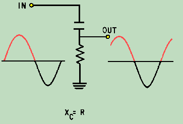
Look for "lockin amplifier".
For phase detect I recommend to generate a second 50% duty cycle signal but withexactely 90° phase shift.
(Easy with a PLD with twice the input frequency).
Use this signal as reference for a second lockin amplifier.
With the output signals of both lockin amplifiers you can calculate amplitude as well as phase shift.
Klaus