Continue to Site

Welcome to EDAboard.com

Welcome to our site! EDAboard.com is an international Electronics Discussion Forum focused on EDA software, circuits, schematics, books, theory, papers, asic, pld, 8051, DSP, Network, RF, Analog Design, PCB, Service Manuals... and a whole lot more! To participate you need to register. Registration is free. Click here to register now.

connecting to SIM900 via terminal

Status
Not open for further replies.

aliyesami

Full Member level 6
Joined
Jan 7, 2010
Messages
369
Helped
0
Reputation
0
Reaction score
0
Trophy points
1,296
Location
USA
Activity points
4,190
anyone with SIM9000 experience ?

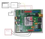
i finally got hold of three SIM9000 modules from various vendors , i am trying to do some basic tests
on them with no luck.
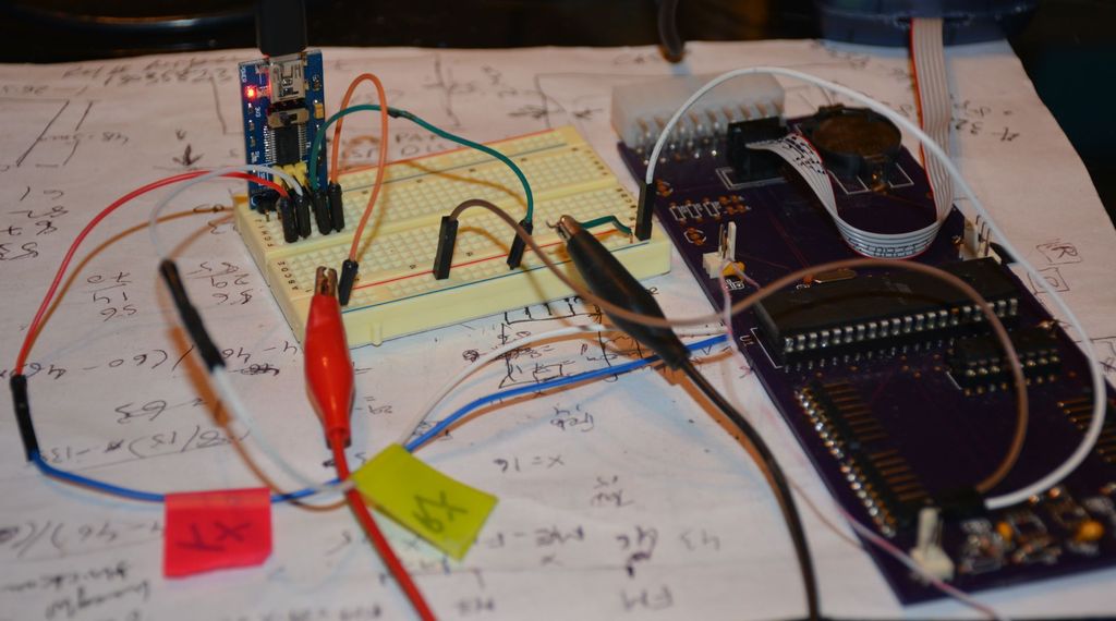
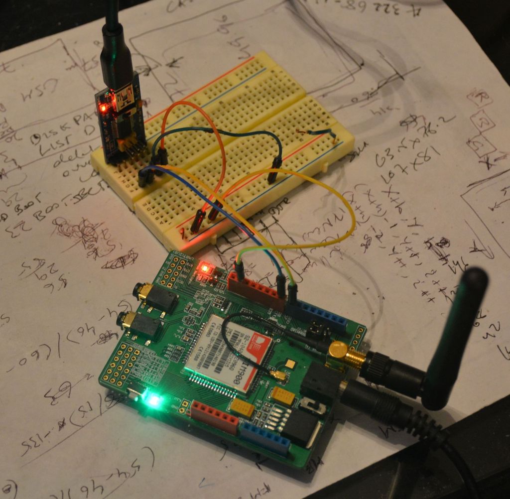
here is what i am doing :running TeraTerm on my laptop connected to the FTDI usb driver , the TX n RX n GND of FTDI module
is connected to the SIM9000 module RX, TX and GND.
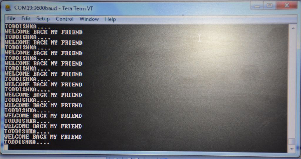
if i give AT commands on the tera term i get no response back from the sim9000 module.

is my basic setup correct ?
what can be going wrong ? does these sim modules have different AT commands?
i am trying AT+CMGF=1<ENTER>

thanks
 

Re: anyone with SIM9000 experience ?

here is the diagram showing how iam interfacing . there are switches on this board i dont knwo what they mean or are they the cause of my problems.
I understand i should get a response from modem with the AT command or i should see startup msgs when i power on the gsm modem , i see neither.
also the baud rate i am not sure on what to set it to.
SIM900_FTDI_interface.jpg
 

Re: anyone with SIM9000 experience ?

I am surprised iam getting no response for this simple thing which so many people are already doing .
 

Re: anyone with SIM9000 experience ?

This may seem like a little thing, but is it possible readers passed over your thread because the title said SIM9000 (with three 0's)?

By doing a search on SIM900 (with two 0's), you'll find that many threads discuss it.
 

I am trying to connect to SIMCOM SIM900 modem using TERTERM n FTDI module but I don't get a response from the modem .
I m only using the RX and TX pins , if I connect my micro I can send serial data to the TERMTERM , so I know that the FTDI module is working .
I have seen videos on youtube of people communicating with these modems from pc using AT commands , wondering what I am doing wrong.
can these gsm modem be talked to using only RX and TX n GND?

thanks
 

Yes, you only need TX, RX and ground but are you sure you are using the correct voltages at the interface?

When you say "FTDI module", do you mean ONLY an FTDI interace or is it a full USB serial interface as used for PC serial links. If it is, it may have an on-board RS232 level shifter which will invert the signals and produce wrong voltages for your application.

Even if your FTDI module produces 5V logic levels, you should really use level shifters to and from the lower voltages used by the SIM module.

Brian.
 

Yes, you only need TX, RX and ground but are you sure you are using the correct voltages at the interface?
yes i am sure the voltages are correct since its a module for arduino and arduino uses 5v right?

When you say "FTDI module", do you mean ONLY an FTDI interace or is it a full USB serial interface as used for PC serial links. If it is, it may have an on-board RS232 level shifter which will invert the signals and produce wrong voltages for your application.
its the raw FTDI interface they sell everywhere with just RX,TX ,CTS, DTR signals. It works fine with my micro and TeraTerm so I know its not the issue.

Even if your FTDI module produces 5V logic levels, you should really use level shifters to and from the lower voltages used by the SIM module.
Brian.

Ideally I should but in non-ideal conditions I should see some communication from the modem like the startup signal or the OK response at the AT command?
 

I have the same modems (SIM900) that you have. I purchased it from LinkSprite (White Board), another Green Board from geektech.com and one more blue board from another source. All look the same.

By default the software UART pins are selected so that when it is used with Arduino you have to use software uart to communicate. I understand that you are just connecting the SIM900 modem's software UART + GND pins to FTDI TTL2USB and then USB to PC.

Just check if the default two jumpers are set to use SW_Tx and SW_RX on the board.

The other thing that you have to do is insert a SIM card at the bottom of the SIM900 board. It has a SIM socket for that.

The last thing is power supply. The board can be powered from External power or Arduino. If you are using External 5V 2A adapter which connects to the DC power jack then set the slide switch to exernal side. If you are using Arduino power pins on the board to power the SIM900 then put the slide switch to XDuino side and then connect power supply (5V 2A) +ve and GND wires to the female header pins. Just stack the SIM900 on Arduino UNO and see which 5V pin of Arduino connect to SIM900 5V pin and which GND pins of Arduino connect to SIM900 GND pins in the female header. You don't need to connect Arduino to power it using female header pin to power the board. I just said to use Arduino to find out the two pins in the female header which can be used to power the SIM900 board.

See image if XDuino power pins are used to power.

Remember whatever be the power source you have to press the power switch for 2 sec. The Net light will start blinking and status LED will light up.
 

Attachments

  • SIM900_FTDI_interface.jpg
    SIM900_FTDI_interface.jpg
    334.9 KB · Views: 160
Last edited:

hi can you see the jumpers in picture if they look good to you ? I think they are set correctly .
I am using external power that came with the adapter 5v 2A.
what baud settings do these modems use? that could also be an issue.
also do you know when I power these modems up do they send some kind of start up message ? in that case I should see those msgs from modem not just the response to the AT commands.

one hopeful thing so far is that if I put the SIM in the SIMCARD socket and turn the power on then the flashing goes to the magical 3 sec rate after it has found the mobile network so modem must be working correctly.
 

As you are using software UART pins which work with the software UART library of the Arduino the jumper settings are correct. These jumper settings make the UART pins of the SIM900 to connect to Arduino software UART pins. I know you are not using Arduino. Arduino is not needed. Your setup should work. As you are powering the SIM900 using 5V 2A power adapter just make sure the slide switch next to power jack is put to the external side. It is written as external and XDuino. on the sides of the switch. When modem is powered on and SIM is present it will output some string like CPIN: and CALL READY. You should see them on the Serial terminal software in PC.

Is your TTL2USB adapter working ? Maybe the TTL2USB is the faulty thing. These SIM900 boards have 5V TTL pins as they are designed to interface with Arduino.

Net and status LEDs should be ON and one will be blinking. The default baudrates of these modems are 9600 bps.

If you want to use hardware UART pins then change the two jumpers to the opposite side. Then you have to interface TTL2USB pins to pin 0 and 1 of the female header.

I have not used the pins you are using to connect it to TTL2USB as they connect to Arduino software UART pins. One thing you can do is intercahnge the Rx and Tx connections and see if that works. It is printed Rx and Tx on the SIM900 board but I don't know whether it is Rx of SIM900 or Rx of Arduino.
 
Last edited:

I have tried swapping the TX n RX pins but still no luck. The FTDI is working fine ,please see the uploaded pics .
The only thing I am doubtful is the ground , can you see if the ground pin iam using is correct ?


- - - Updated - - -

ok I tried ITEAD gsm module same way and that worked fine ,so I am good . i will just use this one and dump the SIMCOM one.
my first experience at GSM modems and what a fun , i have been sending random texts and calling friends since past one hour :)

thanks for your help.
 
Last edited by a moderator:

Status
Not open for further replies.

Part and Inventory Search

Welcome to EDABoard.com

Sponsor

Back
Top