Continue to Site

Welcome to EDAboard.com

Welcome to our site! EDAboard.com is an international Electronics Discussion Forum focused on EDA software, circuits, schematics, books, theory, papers, asic, pld, 8051, DSP, Network, RF, Analog Design, PCB, Service Manuals... and a whole lot more! To participate you need to register. Registration is free. Click here to register now.

series tree or more power supply

Status
Not open for further replies.

ali-libre

Junior Member level 1
Joined
Sep 3, 2015
Messages
16
Helped
0
Reputation
0
Reaction score
0
Trophy points
1
Activity points
107
i'm designing a power supply wit hfour channel
question is that how to design it to series them when needed
IMG_20150904_155931.jpg
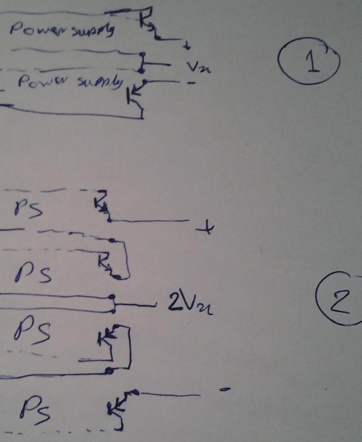
schem 1 will work to provide +-vx
but circuit 2 wil be work...?
how i must design it to series it
 

It is easy if you put DPDT switches at the transformer secondary. You can arrange them to connect windings in series or in parallel.

One switch can control two coils.
 

mmm...
yes , no, thanks for replay
the picture not defind what i was trying to say...
at the end of power supply have dc voltage i draw them bad..
so look at second picture show that we have seprate dc supply

output of them drive by transistor (and a op-amp(emiter folower)).
schematic 1 work but second ...
question is how design it that be possible series them
 

There are yet several steps to cover, between your drawing and a working circuit.

It appears you must turn on the transistors during one half of an AC cycle, to rectify the AC. You will need to bias the transistors at the exact correct moment. Is this your plan? This is not normally done. Normal design is to rectify AC by using diodes.

It will be wise for you to make a schematic of one complete working supply, before trying to make four supplies.
 

my idea is simple & famous , emitter folower or emiter feedback
export.png
for negative supply negative transistor will use(this line writed to prevent spam...!!!)
so how i must design DS supply to series them(more than tow)
pls...
 

1-hmmmm
2-hhhhhmmmmmmmmmmmm
3-hhhhhhhhhhhmmmmm
4- I've read your posts several times, and still don't understand it.

If all you want to do is put 4 transformer windings in series, your "simple and famous" idea is not the way to do it.
 

Your idea would work except that transistors do not conduct in both directions.

There may be components that could do that, but it would require knowledge of part nos., and control circuitry, etc.

The schematic below shows how a DPDT switch can do the job for 2 transformer windings. Its workings are easy to understand.


(The switch is shown as part of a relay because a plain DPDT switch is not provided in the simulator.)

You'll need a second DPDT switch to handle the negative polarity. If you wish to have maximum convenience, you can try to locate a 4PDT switch, but there is no harm if you use two DPDT.
 

Arghhh....i will kill myselfe....:bang:
Thank you for replay...
i dont want series ac supply...
I want series DC supply....DC DC Dc ...
Ok...pls forgot transformers...
Who will use transistor to couple ac...ha...ha...ha... whoare use op-amp to couple ac....
As you can see i can speak enlish very well...so
I have 4 isolate dc supply......2 negative & tow positive...
Each of them will regulate to a voltage using schematic post-5... tow of them can be serise...but i want 4 series regulated dc supply....now please help me...:cry:
 

Status
Not open for further replies.

Similar threads

Part and Inventory Search

Welcome to EDABoard.com

Sponsor

Back
Top