Continue to Site

Welcome to EDAboard.com

Welcome to our site! EDAboard.com is an international Electronics Discussion Forum focused on EDA software, circuits, schematics, books, theory, papers, asic, pld, 8051, DSP, Network, RF, Analog Design, PCB, Service Manuals... and a whole lot more! To participate you need to register. Registration is free. Click here to register now.

Simulation of the Phase locked loop dead-zone using Cadence Virtuoso and spectre

Status
Not open for further replies.

amsdesign

Member level 3
Joined
Aug 26, 2015
Messages
67
Helped
0
Reputation
0
Reaction score
0
Trophy points
6
Activity points
550
Hi I'm trying to simulate the dead-zone present in the phase frequency detector of a PLL. However, I get these waveforms

dead_zone_error.JPG

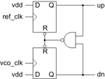
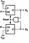
Here is the circuit diagram of the phase frequency detector. The FFs in my simulation have a reset that need to be set to LOW. So I'm using a NAND gate and Z is the output of the NAND gate.
pfd.png

However, for any amount of phase shift, I see ringing on the nodes. Why exactly is this happening?
 
Last edited by a moderator:
The FFs in my simulation have a reset that need to be set to LOW.
You should correct the schematic for clarity, but I see that you are actually using a NAND gate in simulation.

There's apparently a problem with the reset timing of the DFF model, it seems to expect a longer signal duration. Adding some delay in the reset path should fix the issue.
 

Hi FvM,

Thank you for the solution. It worked now.
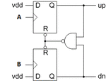
Here is the proper schematic:

PFD.gif
However, there are still some problems.


Here are the specs for pulse generators A and B.
Period : 2us
Width: 1us
Rise/Fall : 50ns

UP is QA

If there is a delay of 1us between A and B, UP(QA) is able to capture the phase difference (after I added the delay block of 1us in the reset path)
Waveform:
phase_capture.JPG


However, for a smaller delay , say 500ns, and a delay block of 500ns in the reset path, I get this waveform. A 500ns phase difference captured on UP(QA), but I also get another pulse for 500 after that. The same goes for any phase delay less than 1us.
increased_dz.JPG


Why do I get this additional pulse on UP(QA)?
 

Attachments

  • PFD.gif
    PFD.gif
    4.3 KB · Views: 111
Last edited:

If have no idea about the speed of involved logic. What's the frequency of the oscillation in the initial post?
 

If have no idea about the speed of involved logic. What's the frequency of the oscillation in the initial post?

The same.
Period : 2us -->500Khz
Width: 1us
Rise/Fall : 50ns
 

No. I'm talking about the fast oscillation frequency which is most likely far above 100 MHz. It gives an idea of the required additional delay in the reset path.
 

No. I'm talking about the fast oscillation frequency which is most likely far above 100 MHz. It gives an idea of the required additional delay in the reset path.

I don't understand. Fast oscillation frequency?
 

It looks like the reset path is too fast to achieve a stable self-reset of the DFFs, resulting in a fast oscillation. Delaying the reset signal by the minimal reset pulse width (e.g. 10 ns) would help.

osc.PNG

There may be also a problem with the DFF design. When the DFF comes out of reset, a static high level at the clock input must not be recognized as a new rising edge. You can check this in a separate simulation.
 

Yes, I did add a reset and for phase differences >1 uS the PFD generates the phase difference of the two signals.
But for a phase difference <1us I see multiple pulses with width equal to the phase difference being put out on QA. Why that peculiar behavior?
 

A delay of 500 ns or 1 us in the reset path is unsuitably high. Seeing still unwanted behaviour with a large delay suggests that the DFF isn't operating as expected.

I checked with a standard HC74 circuit, a statically high clock input won't retrigger after releasing the reset because a transmission gate disconnects the D input while C = 1. The standard PFD circuit can be expected to work correctly with HC74.
 
So, the problem is with the FF?
 

It seems so. As said, a simulation of the standalone DFF should clarify things.
 

Status
Not open for further replies.

Part and Inventory Search

Welcome to EDABoard.com

Sponsor

Back
Top