Continue to Site

Welcome to EDAboard.com

Welcome to our site! EDAboard.com is an international Electronics Discussion Forum focused on EDA software, circuits, schematics, books, theory, papers, asic, pld, 8051, DSP, Network, RF, Analog Design, PCB, Service Manuals... and a whole lot more! To participate you need to register. Registration is free. Click here to register now.

single stage buck boost inverter

Status
Not open for further replies.

manumario

Newbie level 2
Joined
Sep 2, 2015
Messages
2
Helped
0
Reputation
0
Reaction score
0
Trophy points
1
Activity points
20
Hi engineers,

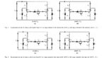
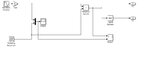
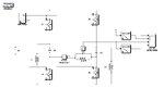
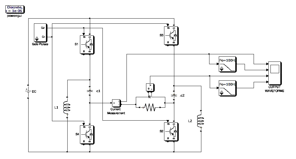
need help to design a single stage inverter for my academic project, i tried so much to design it by myself and failed. now am helpless, I dont know much about power electronics so you may found me as a noob. sorry for that. Circuit diagram of the inverter is attached
 

Attachments

  • in.jpg
    in.jpg
    124.3 KB · Views: 90
  • base paper.pdf
    1.7 MB · Views: 84
  • gate.jpg
    gate.jpg
    26.2 KB · Views: 98
  • circuitBB.jpg
    circuitBB.jpg
    53.7 KB · Views: 89

new buck boost inverter

hi all,

i designed a buck boost inverter which can generate step up and step down output using spwm switching by varying modulation index, the circuit has symmetrical nature but the output of the system is proper only in positive half cycle. in negative side it is just inverting the input voltage there is no step up or step down occurring in negative circuitBB.jpg


Your schematics are more complicated than they need to be. They appear to be a convertible design, with many switching devices, so that you can operate them in various patterns and make them function as different types of converters.

It would be better if you start with the simplest possible buck-boost design. That is, the minimum number of components, one switching transistor, etc.

To further understanding, I have a video on Youtube which portrays basic simulations of three switched-coil converters (buck, boost, buck-boost). They are animated, portraying current flow through wires, flux field growing and collapsing, and capacitor charging and discharging.

Clicking this thumbnail should work:


Or else at Youtube:

www.youtube.com/watch?v=FT_sLF5Etm4
 

here is inverter simulation in ltspice, it is cuk inverter. just convert to .asc and run
 

Attachments

  • lt1617-1.txt
    2.3 KB · Views: 42
  • Like
Reactions: FvM

    FvM

    Points: 2
    Helpful Answer Positive Rating
The original circuit is an inverter converting DC to AC voltage. I presume manumario want's this circuit function.

Post #3 and #4 are suggesting DC/DC converters.

I don't understand which problem with the circuit is described in post #1 and #2. Just notice that the LC output filter has been omitted from the original paper.

I would expect simulation waveforms visualizing the problem.
 

Status
Not open for further replies.

Similar threads

Part and Inventory Search

Welcome to EDABoard.com

Sponsor

Back
Top