Continue to Site

Welcome to EDAboard.com

Welcome to our site! EDAboard.com is an international Electronics Discussion Forum focused on EDA software, circuits, schematics, books, theory, papers, asic, pld, 8051, DSP, Network, RF, Analog Design, PCB, Service Manuals... and a whole lot more! To participate you need to register. Registration is free. Click here to register now.

Metal Heatsinking for SMPS transformers suffers eddy current losses?

Status
Not open for further replies.
T

treez

Guest
We have a 3kw offline battery charger which we bought and they keep stopping working.
We therefore took it apart, and we noticed a 3kW LLC converter using a transformer of Epcos PQ35/35 dimensions and shape. (yes, it was really THAT small!)
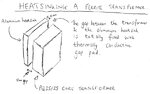
Anyway, this transformer is thermally coupled to a 5mm thick aluminium plate heatsink as in the attached diagram.
Surely having a metal plate close to the open side of a high frequency transformer (the PQ35/35 core is not shielded) is going to result in too much eddy current heating in the aluminium heatsink?


Epcos Ferrite databook shows PQ35/35 core on page 281:
https://en.tdk.eu/blob/519704/download/2/ferrites-and-accessories-data-book-130501.pdf
 

Attachments

  • Heatsinkin a ferrite transformer.jpg
    Heatsinkin a ferrite transformer.jpg
    82.5 KB · Views: 134

Not clear what you mean with "not shielded"or "open side". The core has a closed magnetical path, the field at the outer surfaces isn't large.
 

by "open side", I mean the side where if you hold it in front of you, you can see the windings with no ferrite core covering them. (as opposed to the ends where one cannot see the windings as there is ferrite in the way)
Being "open", it means there is no ferrite to "absorb" the field lines, so the high frequency changing field can propagate to the aluminium heatsink, and cause eddy current losses there. Surely this is bad?
 

They have done this to conduct some of the heat from the wires to the Al plate, there will be minimal heating of the Al plate due to fringing flux of the Tx, unless it has a large gap in it, and even then the heating will be <50mW due to this effect (due to the separation)...
We have put 2.7kW thru an RM14 in a commercial design that required long periods at full power (250kHz).
 
  • Like
Reactions: treez

    T

    Points: 2
    Helpful Answer Positive Rating
What is the hotspot temperature rise at full load?
What is the surface linear air speed?

I suspect the eddy current losses are diminished with the 5mm thermal conductive dielectric gap.

edit

PQ35/35 has been discontinued since 2011 yet PQ40/40 is not. Cores must be burnished prior to assembly.
 

It's doubtful that it causes significant losses, and any extra losses that do occur should be negligible compared to the amount of heat the plate removes. In SMPS transformers it's common to include RF and safety screens between winding layers, and to my knowledge they don't cause substantial dissipation, despite being much closer to the windings.

The bigger question about such a setup is what it means for EMC. If that aluminum plate is bolted to the chassis, then it is going to carry a lot of EMI into the earth circuit.
 

Status
Not open for further replies.

Similar threads

Part and Inventory Search

Welcome to EDABoard.com

Sponsor

Back
Top