Continue to Site

Welcome to EDAboard.com

Welcome to our site! EDAboard.com is an international Electronics Discussion Forum focused on EDA software, circuits, schematics, books, theory, papers, asic, pld, 8051, DSP, Network, RF, Analog Design, PCB, Service Manuals... and a whole lot more! To participate you need to register. Registration is free. Click here to register now.

Improving resistor string DAC speed and INL linearity

Status
Not open for further replies.

ansonyeap

Member level 2
Joined
Oct 29, 2009
Messages
46
Helped
1
Reputation
2
Reaction score
1
Trophy points
1,288
Activity points
1,668
Dear all,

I have designed a 8 bits DAC with folded R-string structure.

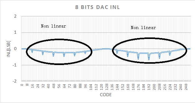
however, I notice that the output INL linearity degraded as shown in the picture below:


I check one of the settling time of the code transition i.e from Code0 to Code32, the output settling time is more than 0.5us.

Currently I am using the same size transmission gate as the switches to select the output.

My DAC output is driving a capacitor load of 10pF.

Is there anyway to further improve the settling time to around less then 0.2us? as my DAC have to work at speed more than 4MHz.

thank you
 

Hi,

This is an INL of about 0.3 LSB and a DNL of about 0.4 LSB.
The maximum is below 1 LSB, so why bother. Does further improvement really significantly improve overall performance?

Klaus
 

Hi KlausST,

Ya...

FYI, The DAC will be used to provide a sine wave, so better improve it further so that the sine wave linearity will be as closed to ideal as possible.

in addition, I expect it to become worse across PVT, that why I need to further improve it. the design target for INL is less than 0.5LSB for all condition.

Any suggestion? by right the RC delay is the worse at middle code setting, however, this is not the case in my simulation.
 

Hi,

with 8 bit coding you always have an +/- 0.5 LSB error at ech conversion.
So it is OK to keep addidtional errors below that. But it is already in this region, therfore - to keep effort to quality ratio low - my next step would be to increase bit resolution.

Yes, with this design the time constant is highest a center. What if you try to connect a unity gain bufffer inbetween DAC output and filter?

It doesn´t look like the load is the cause of your INL, but with the buffer you can check on this also.

***
The DNL seems to come from the multiplexers. Do you have some mux in series?
Maybe the MUX(es) also cause the INL?
***

What analog output frequency range do you expect?

Klaus
 

Hi KlausST,

I previously got try to remove the Cload(10Pf) at the DAC output and the linearity is very good.

I also notice that the TG Switches RON is low at 3 region, i.e low voltage, Mid voltage and highest voltage when sweeping the VIN from 0V to 6V.

I suspect the non-linearity between low code to mid code setting is due to RON is start to rise and fall again when reach mid code setting. the same trend go to the mid code to full code.

Correct me if I am wrong?

Yaya.. I am using the mux in series to connect the desired tab voltage to the Cload(10Pf)

Basically I want the Output to be able to settle within +/-0.5LSB when code setting changes from one to another in 250nS period.

Thank you
 

Hi,

Sounds good.

The Ron you tell makes sense, especially when connected in series, then the errors multiply.
And the DNL.
Could you try without series connection.
Btw: is it simulation or real live?

Did you test it with a buffer?

Klaus
 

Hi KlausST,

the design is based on folded resistor string design, therefore the series connection will be needed to get the desired output.

without the series connection, I cannot get the output.

No.. I does not test with buffer as the design later will be connected to a buffer, thereforem the 10pF load is for the buffer input stage load

I doing the simulation in cadence for 0.11 process which later on will be fabricated.
 

Status
Not open for further replies.

Similar threads

Part and Inventory Search

Welcome to EDABoard.com

Sponsor

Back
Top