Continue to Site

Welcome to EDAboard.com

Welcome to our site! EDAboard.com is an international Electronics Discussion Forum focused on EDA software, circuits, schematics, books, theory, papers, asic, pld, 8051, DSP, Network, RF, Analog Design, PCB, Service Manuals... and a whole lot more! To participate you need to register. Registration is free. Click here to register now.

Question: DC analysis of a transistor amplifier?

Status
Not open for further replies.

samy555

Full Member level 4
Joined
May 11, 2010
Messages
207
Helped
0
Reputation
0
Reaction score
0
Trophy points
1,296
Location
Palestine
Activity points
2,963
Hi

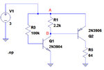
I could not complete the analysis of this circuit.
w1.jpg

This is what I managed to do:
IB1 = (VCC - VBE1)/R3 = (3 - 0.7)/100K = 23uA
If β = 100, then IC1 = 2.3mA
VCE1 = VCC – IC1 * R1 = 3 – (2.3m* 2.2K) = - 2.06 V (Error)
The Voltage between points A & B (VAB) = 0.7 volt
So, IC1 = VAB/ R1 = 0.7/2.2K = 0.318 mA
Then, VCE1 = 3-0.7 =2.3 V
I stopped here. I wish I could calculate IC2 and VCE2 to complete the picture.
Thank you.
 

Samy - you must not start your calculation with IB1.
More than that, your assumption beta=100 is an assumption that cannot be valid because the voltage across R1 is restricted to be in the region of 0.65..0.7V.
From this, you arrive at an Ic value which is much smaller than 2.3mA. But don`t forget the base current for T2 which also gows through R1.
 
Last edited:

No, you absolutely should start with Ib1, and yes arrive at Ic1 = 2.3 mA (or up to 6.9 mA with maximum 2N3904 current gain). Most of it will flow through base-emitter junction diode of Q2. Ib2 is about 2 mA, Ic2 limited to about 45 mA by R5, so Q2 is saturated.
 

Yes - FvM, you are right. For the moment, I didn`t realize that Q2 is pnp with an Ib that is opposite to the Ib from Q1. Sorry. Next time I will try first to think and then to answer.
 

You do not need equations, simply use children's arithmetic with Ohm's Law.
I gave details at the Electro-Tech forum.
 

I want equations ??

Samy, before continuing - are you sure about the circuit? My question is because, normally, in such a combination of two transistors the transistor Q2 is in emitter-follower configuration (64 Ohms in the emitter path).
Please, check again.
 

You do not need equations, simply use children's arithmetic with Ohm's Law.
I gave details at the Electro-Tech forum.
I see that, thanks

- - - Updated - - -

Samy, before continuing - are you sure about the circuit? My question is because, normally, in such a combination of two transistors the transistor Q2 is in emitter-follower configuration (64 Ohms in the emitter path).
Please, check again.

T3 and T4
https://circuitdiagram.net/wp-content/uploads/2012/02/Cheap-Hearing-Aid-Circuit-Diagram.jpg
 

Although ear phone resistance isn't given, that's a really bad design.

BC548/BC558 current gain has even a possible range up to 800, so it's effectively impossible to define T4 bias by a T3 base resistor, particularly if you need it to be in linear range. You would use at least transistors with selected current gain, e.g. A group.
I have tested the circuit and was very successful
I did a single modification on the circuit
I used a single weak battery instead of a pair of batteries, so Vcc = 1.2V
 

The circuit is hopeless but you might be lucky with it.
1) You NEVER bias a transistor like that because transistors have a range of hFE DC current gain and the transistors you buy might have low hFE of 100 and be almost cutoff or have a high hFE of 800 and be saturated.
2) Since the transistors have no negative feedback then sounds will be extremely distorted.
3) The mic is an electret mic, not a condenser mic.
4) The input impedance of the first transistor is too low and shorts away most of the output from the mic.
5) The circuit is supposed to be a hearing aid but it boosts all frequencies the same amount. But a hearing aid usually boosts only high audio frequencies.
6) The circuit has DC current in the earphone that might damage it, it might force its membrane to one end which mutes it and it wastes battery power.
 

Since I thought this good question deserved a better answer when I looked again on ETO, so I copied my answer here.

I don't see it as a bad design.
I rather think it is a fairly good design that needs to be analyzed with experience.

It is just an analysis of a non-inverting High-side switch.

** See edit at end **

Zin = 100K input impedance
Zload =64Ω load
Vin = Vcc=3V

The load could be a high power relay coil or some other active load.
Each resistor is calculated carefully based on assumptions for the current gain hFE when in linear mode for the 1st stage and when saturated in the second stage as a switch. Unfortunately some interpolation for hFE vs Vce needs to be done from the data sheets, so I'll explain this later.

Let's start with a simple analysis and explain the assumptions.
We know that Vbe starts below 0.6V and rises above 0.7V when Vbe gets saturated due to intrinsic bulk resistance and often well beyond at rated base current.

1. From std. datasheets, hFE= 200 nominal for both Q1 & Q2
2. Let Vbe1= 0.6V since base current is very small (3-0.6V)/100k= 24 μA,, but Vbe will be 0.7V or more, assume 0.7 now.
3. Ic1 = 200*24uA = 4.8mA minus the current thru R1, which was designed to be a bit more than 5% of Ib2 ,

I_R1 = Vbe2/2.2k = 0.32mA so Ib2 = 4.5mA
almost 95% of collect current ends up driving Q2, which is good for a sensitive fast switch.

4. The main trick here not taught in school, is that when Transistor Vce saturates, they are always rated at only fixed current ratios like Ic/Ib=10 or 20 or 50 .

then they give the Vce(sat) result at two current levels for Ic/Ib=x, so you may have to interpolate.
If you design for Ic/Ib= spec ratio, then you can get specific range of results for Vce(sat).
The trick to remember is that when saturated, the current gain tends to be around 10% of the linear hFE for a reasonable low Vce(sat).
So we are going to use a current gain of 10% of 200 or Hfe(sat) = 20 to compute Ic2.

5. We conclude that Q2 is saturated, because Ic2= 20x4.5mA=90ma . if linear across R5 would be 5.76V

Since Vce2 is saturated R5 should be near 2.9V thus Ice2=2.9V/64Ω= 45mA
we see from the datasheet for a ratio of 10:1 is used to give Vce(sat)
here Ic/Ib= 45/4.5mA .. Eureka 10:1 ratio was used.

R1 serves a purpose when the input goes low to speed up the switch off time.

For a quicker analysis we see Q1 will never saturate as the collector is always 1 diode drop below Vcc
We see that will saturate Q2 if the load current/base current is 10:1

So to recap, we calculate
Ib1
hFE*Ib1=Ic1
assume Q2 saturates with no Collector feedback then verify Ic/Ib ratio for Q2
then Ic2~ Vcc/R5
then Ib2= Ic1- 0.7/R1 and Ic2/Ib2 is pretty close to exactly 10.
If 20 was used, some devices might give Vce2=0.2 instead of 0.1 , but note in the datasheet the worst case is given as;

@25'C
V CE(sat) Collector-Emitter Saturation Voltage
(Ic =10mAdc, I B =1.0mAdc) 0.25V max dc
(Ic =50mAdc, I B =5.0mAdc) 0.4V max dc

2nd iteration.

Since Ic = 45 is pretty close to 50mA we can expect worst case slightly less than Vce2=0.4 and typical since not given, might be half of max.

So we would say Vc2 on R5 is between 2.6~2.9V or 2.75 +/- 0.15

Good for a switch... lousy for an audio amp

EDIT** after reviewing the thread I see it is part of an audio amp and earphones can have a much lower DCR than 64Ohms which means Q2 comes out of saturation. But if the DCR is only 64 Ω, we can only get positive swing of 0.4 to 0.1. But if it was like 10Ω DCR with an AC impedance of 64 Ω then we would be running Q2 in a Class A (quasi) linear mode.

So what is the Rce or output resistance of Q2 ?
We see from DC Current Gain vs Collector Current at Vce=1V that at Ic=45mA, hFE drops from 200 to 160. which is a rise from 20 when saturated.
Thus to improve the design, we can operate it from 1.5V battery , as I see you have done.

or reduce R1 to starve Q2 of collector current or even better use regenerative feedback by adding an RE to Q2.

- - - Updated - - -

Never try to choose transistor with hFE of 200 to 800 nor substitute it with ones averaging 200 and give a partial schematic without a purpose or source impedance or real load impedance... so I dont embarass myself. hahaha
 

I have tested the circuit and was very successful
I did a single modification on the circuit
I used a single weak battery instead of a pair of batteries, so Vcc = 1.2V
The "single modification" changes the operation point completely, there's now a good chance to hit a linear operation point with typical transistor current gain values.

In other words, successful operation of the presented circuit is more or less by accident. With less luck, you have to adjust resistor values for each amplifier exemplar.
 

This may be better for you, and still cheap.

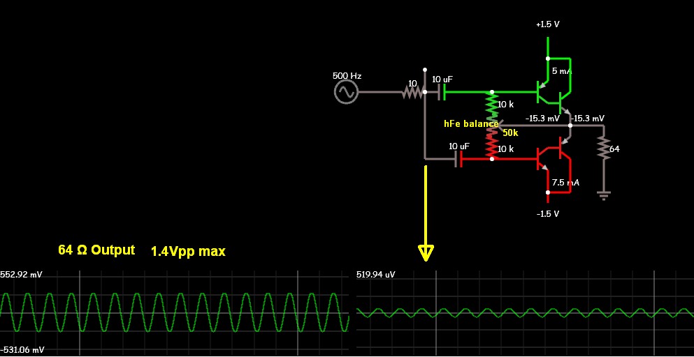
Voltage Gain = 1000= 60dB with 64 Ohm load. Zin =32
Pot added to balance hFE between NPN and PNP,
hfe >300 suggested
Design chosen for max voltage gain but no impedance gain.
Previous stage must be complementary emitter follower. then it can be DC coupled instead of AC coupled.

Batteries are split to load. +/-1.5

1713291100_1439935702.jpg


- - - Updated - - -

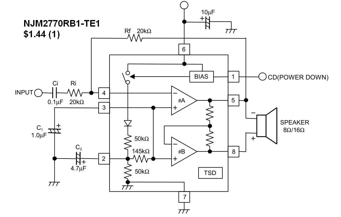
If you really want to re-invent the wheel and find out it squeaks of draws too much current or is too distorted.

Otherwise, Integrated solutions are far superior. Gain controlled by fixed R values added with Vcc 2~5V ,PSSR = 50 dB, 0.1nA in power down mode, 85dB gain open loop, Vout=0.95 to 1.25Vpp @3V, 0.1% THD @ 100mW

And only $1 in 100pc
9587275500_1439938091.jpg
 

Status
Not open for further replies.

Similar threads

Part and Inventory Search

Welcome to EDABoard.com

Sponsor

Back
Top