Continue to Site

Welcome to EDAboard.com

Welcome to our site! EDAboard.com is an international Electronics Discussion Forum focused on EDA software, circuits, schematics, books, theory, papers, asic, pld, 8051, DSP, Network, RF, Analog Design, PCB, Service Manuals... and a whole lot more! To participate you need to register. Registration is free. Click here to register now.

Matching section design of Single ended FET mixer

Status
Not open for further replies.

muheeb16

Member level 3
Joined
Jul 18, 2015
Messages
55
Helped
1
Reputation
2
Reaction score
1
Trophy points
8
Activity points
416
I am designing a single ended FET mixer using atf21170 and I have isolated the RF and LO port by a bandpass filter,at the output I am using a 6th order chebyshev low pass filter.The major problem that I am facing is that of designing the matching section at the input.I don't know how to begin with that.Will someone please help me here?I do not want to use any other device model because I am almost done with this project.Just the mystery of matching section remains to be solved.I have the S-parameters available at my desired frequencies. schem.PNG
 

It's not a good idea to separate LO and RF signal by diplexer or something else. You won't able to obtain enough isolation between them. They will impact/disturb each other.While RF signal is driven at Gate side, LO signal can be fed ( or vice versa) to Source to mix-up the signals to obtain mixing products. Your circuit is very primitive and achieve a good performance is pretty difficult.
 

But what about the matching section?This is just a schematic.
 

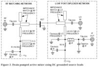
When using single FET as a mixer the best isolation that you can get is when using drain pumped LO. The diplexer in this situation is between LO and IF.

**broken link removed**

 
match.PNG
Here's what I want to know:
I designed a low nose amplifier at 5.5GHz recently and here's what I did.I had to set my Reflection coefficient looking toward the source=optimum source reflection coefficient for obtaining minimum noise figure and I used conjugate matching at the load for obtaining maximum possible gain.
Now,in case of mixer I don't know how I should design my matching sections at the LO and RF frequencies.What should I set the values of reflection coefficients?
 

Status
Not open for further replies.

Part and Inventory Search

Welcome to EDABoard.com

Sponsor

Back
Top