Continue to Site

Welcome to EDAboard.com

Welcome to our site! EDAboard.com is an international Electronics Discussion Forum focused on EDA software, circuits, schematics, books, theory, papers, asic, pld, 8051, DSP, Network, RF, Analog Design, PCB, Service Manuals... and a whole lot more! To participate you need to register. Registration is free. Click here to register now.

Improved Howland Current Source

Status
Not open for further replies.

anushaas

Member level 5
Joined
Jan 4, 2011
Messages
84
Helped
0
Reputation
0
Reaction score
0
Trophy points
1,286
Activity points
1,979
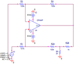
I am trying to design a 500uA current source using LMC6492.The circuit that I tried simulating is attached along with.

HCP.png

I understand that the expression for the output current of an enhanced Howland current source i = [(R2A+R2B)/(R1*R2B)]v.As per the resistor values chosen,with an input of Vamp =10V,the current should be 10 mA theoretically,but simulation results shows a current of 50uA.

Can anybody tell me where I am going wrong?
 

Why did you apply Vin=10V to an Op AMP with only +/-8V supply with x1 gain.

If you want 10mA out use Vin=1 and R2B= 100.

Examine your choice of load and voltage drop .
if R5=10k then Op Amp would need to supply 10mA*10k= 100V to generate this output.

The linear operation of this voltage to current convertor requires that you stay within the linear operating limits.

Vin / R2B=Iout
Since R2B is 1k , it you want 500uA, Vin must be 500mVdc.

You are right.I shouldn't be using a 10V input.Thank you.
But even with a reduced input of 0.5V,Iout is coming as 2uA(peak value) and not 500uA
 

Check voltage on all pins.
If Vin=0.5V and you expect 0.5mA into R8=10k then V(R8) = 5V,
then Pin 2=Pin3 = (5-0.5)/2= 2.75V and Pin 1 = twice this or 5.5V on output, giving 0.5V drop across R2B.
 

The expected load variation is 10 Ohm to 10 kOhm,So with 0.5mA,the load voltage drop will vary from 5 mV to 5V.Also the input is a sinusoid not dc as I want an alternating current source.

With an input sine of 0.5V amplitude,the voltage at pin 3 is about 250 mV(amplitude) but at pin 3 it is only 10 mV(amplitude)
 
Last edited:

Here's an LTspice simulation of your circuit.
The output is 1mA for 1V input, for a load varying from 10 ohms to 10k ohms.

Howland.GIF
 

For an input sine of amplitude 0.5V and frequency 50Hz,these are the pin voltages

PIN 1: 5 mV(amplitude) ac
PIN 2: 2.5 mV(amplitude) ac
PIN 3: 250 mV(amplitude) ac
PIN 4: -8V dc
PIN 8; 8V dc

Load voltage(across R6 which is now 2k) is 5 mV(amplitude) ac and Iout is 2.5 uA(amplitude) ac.

I have also changed R1 to 101k as suggested.I am using the OrCAD PSpice tool for simulation

- - - Updated - - -

I replaced the LMC6492 with a default OpAmp and it worked perfectly as expected.
 

Not obvious at first sight why the circuit isn't working with LMC6492, but having different voltage at inverting and noninverting inputs indicates clearly that the OP is out of regular operation.
 

Improved Howland Current source

Hi,

I am designing a 500uA current source using AD8041(160 MHz –3 dB Bandwidth (G = +1)).I need a wide frequency range for the current source(say DC to 2MHz).

The circuit attempted is as shown below.When implemented,it gives a -3dB bandwidth of 0.25 MHz.How can I improve the frequency response such that I get a 500uA current through my load even at a high frequency,say 2MHz?
 

Attachments

  • IHCS.png
    IHCS.png
    6.1 KB · Views: 95
Last edited by a moderator:

The circuit attempted is as shown below.When implemented,it gives a -3dB bandwidth of 0.25 MHz.
It's not understandable how the shown circuit should have only 250 kHz bandwidth with AD8041 and 2k load. Something must be different.

There's however a problem with 100k feedback resistors and OP input capacitance. The circuit is likely to show stability issues. 100k isn't a suitable resistor level for a 160 MHz OP. You'll need a least a small compensation capacitor as shown in the first post of the original thread.
 

Re: Improved Howland Current source

Hi,

The circuit attempted is as shown below.When implemented,it gives a -3dB bandwidth of 0.25 MHz.

By saying "when implemented", do you mean that you have actually built the circuit?
If so, do you have oscilloscope waveforms we can take a look at?
 

Yeah.I tried implementing the circuit on an NI ELVIS II board.

I tried the same circuit configuration as shown above but used 1k resistors in the negative input side and 2k in the positive input side.Load resistor was 12k.

The frequency response plot obtained is as shown below:
Bodeplot.png

The same circuit was attempted with an additional 6.8pF capacitor in parallel to resistor between pin 2 and 6.

The response is as shown below:
Bodeplot with 6.8pF capacitance.png

The -3dB frequency in these cases has improved and is approximately 1MHz.

How can I improve it further to 2MHz?
 

The bandwidth according to OP data would be higher, about 3.5 MHz. We can only guess that parasitic circuit capacitances of your breadboard make the difference. It's not suitable for a 160 MHZ OP.

It would be helpful to see the complete test circuit, including the probe connection. The cut-off frequency doesn't move much when you are changing the compensation. The result makes me guess that you have a "hidden" capacacitor of about 25 pF parallel to the 12k load, may be a probe connection.
 

Thank you but how you made that guess??.

I am using a Tektronix TPP0200 voltage probe across the load.

Its spec is as follows:200MHz,10MOhm/<12pF,10X
 

If I modify the circuit by using a voltage follower as shown below,should I be doing the impedance matching?

If yes,would it be fine if I put a 2k resistor after voltage follower as shown here?

IHCS.png
 
Last edited:

Status
Not open for further replies.

Part and Inventory Search

Welcome to EDABoard.com

Sponsor

Back
Top