Continue to Site

Welcome to EDAboard.com

Welcome to our site! EDAboard.com is an international Electronics Discussion Forum focused on EDA software, circuits, schematics, books, theory, papers, asic, pld, 8051, DSP, Network, RF, Analog Design, PCB, Service Manuals... and a whole lot more! To participate you need to register. Registration is free. Click here to register now.

LC filter design brainstorm

Status
Not open for further replies.

bowman1710

Full Member level 3
Joined
Nov 8, 2014
Messages
183
Helped
6
Reputation
12
Reaction score
6
Trophy points
18
Activity points
1,604
Hi guys,

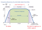
I am trying to come up with a decent filter that will block HV DC and stop any AC signals above 10KHz with high gain as possible as per attached image, really I need an LC filter design. Any ideas/brainstorms welcome.

thanks

filter.png
 

Any decent design deserves a spec.


  1. HVDC max =?
  2. Pass Bandwidth is defined by -3dB points
  3. you have LPF=10kHz
  4. and HPF=?
  5. minimum passband gain =?
  6. Band Reject f and attenuation is ?
 

Hi SunnySkyguy,

HVDC max =400V

As for other details as attached

filter 2.png

In post #1 i meant to say high attenuation not high gain by the way.

I have tried other designs with LC low pass but I has issues with using the T-shaped low pass filter that the VDSL signal would not work because there was a direct short to ground with the caps needed for the 1Khz signal.
 

How much voltage/current on the AC source?
 

the sine wave that will be passed through will be around 5V at 100mA max
 

Then you're going to need a very large capacitor for the DC blocking. Around 50uF to meet that 100Hz cutoff with a 50ohm load. Something like this. After that, a simple lowpass LC filter using lower voltage components will be fine. Keep in mind the filter response will depend greatly on the load impedance.
 

Hi SunnySkyguy,

HVDC max =400V

As for other details as attached

View attachment 119730

In post #1 i meant to say high attenuation not high gain by the way.

I have tried other designs with LC low pass but I has issues with using the T-shaped low pass filter that the VDSL signal would not work because there was a direct short to ground with the caps needed for the 1Khz signal.

Ok the next spec required is source , input, output and load impedance over entire range of audio and VSDL to avoid interference.
assume it is high impedance above 50MHz but need to know impedance to avoid resonant, same with Csource =? in audio at 1Khz
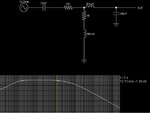
 

A series LC acts as a bandpass filter. It blocks DC.


The values shown determine the center frequency as about 1000 Hz.

By changing the L:C ratio, you can change the steepness of the rolloff curve.
 

Ok the next spec required is source , input, output and load impedance over entire range of audio and VSDL to avoid interference.
assume it is high impedance above 50MHz but need to know impedance to avoid resonant, same with Csource =? in audio at 1Khz

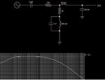
Until you define source and load impedance, I assumed Cin, Rin and Cout and the rest was added to meet your requirements. The L, 100 mH is rather large, depends on the 100 Ohm source and has internal Rs of 10 Ohms to achieve the flat response. Lower Rs would sharpen the low end and much higher would degrade attenuation.

rlc VDSL.jpg

This plot is from 10 Hz to 25Mhz and is 20dB/decade at both ends.

Then again 100mH will have a lot of self capacitance and low SRF which improves high end attenuation and degrades low end.
rlc VDSL2.jpg
 

Until you define source and load impedance, I assumed Cin, Rin and Cout and the rest was added to meet your requirements
.

I am trying to work this out, the signals will be coupled onto a 50ohm single coaxial cable over different lengths so its hard to initially see what these will be, i dont know how much the different lengths will effect this.

100 mH is rather large
I do not have much room to play with so 100mH will be way out of the question

A series LC acts as a bandpass filter. It blocks DC.

this is one of my options i have at the minute, to save components/size

After talking about it, this seems to work does anyone see any issues, flaws with it?

idea.png
 

You ended up with a regular third order low-pass + coupling capacitor (= first order high pass), plausible so far. It can be tuned according to your specification which was yet clearly given.

Two comments:

- you may want to use a finer frequency increment than 1 point per octave in SPICE simulation

- I understand that it's telephone line problem. You should add realistic line impedances to your simulation, otherwise the results won't have much to do with real live. Why did you select 50 ohms load impedance?
 

your specification which was yet clearly given.

What more is needed from posts #1, and #3???Apart from what SunnySky mentioned?

source , input, output and load impedance over entire range of audio and VSDL to avoid interference.

With it connected to a 50 Ohm coaxial cable will these all ideally be 50ohm for impedance matching??


You should add realistic line impedances to your simulation, otherwise the results won't have much to do with real live. Why did you select 50 ohms load impedance?

The 50ohm is for a 50hm terminated co-axial cable, am i incorrect in putting 50ohm for the load impedance for this??:?
 

What more is needed from posts #1, and #3???Apart from what SunnySky mentioned?
Exactly this. Let's assume 10 kHz cut-off frequency is O.K., also third order slope (18 dB/octave), then acceptable passband ripple/gain deviation should be specified.

I agree that 50 ohm load impedance is a reasonable choice, but only if the source impedance isn't much greater than 50 ohms. This won't be the case for a telephone line. Load impedance must be known for an exact calculation of filter characteristic anyway.
 

I agree that 50 ohm load impedance is a reasonable choice, but only if the source impedance isn't much greater than 50 ohms. This won't be the case for a telephone line. Load impedance must be known for an exact calculation of filter characteristic anyway.

The cables characteristic Z will be 50R so for all source,input,output and load will be around 50R too.


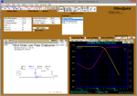
This is what I get from FilterQuick that I have downloaded today.

Idea2.PNG
 
Last edited:

Status
Not open for further replies.

Similar threads

Part and Inventory Search

Welcome to EDABoard.com

Sponsor

Back
Top