Continue to Site

Welcome to EDAboard.com

Welcome to our site! EDAboard.com is an international Electronics Discussion Forum focused on EDA software, circuits, schematics, books, theory, papers, asic, pld, 8051, DSP, Network, RF, Analog Design, PCB, Service Manuals... and a whole lot more! To participate you need to register. Registration is free. Click here to register now.

[SOLVED] PWM which is working before stop working after adding other peripheral

Status
Not open for further replies.

urnuj

Junior Member level 3
Joined
Jul 16, 2015
Messages
27
Helped
1
Reputation
2
Reaction score
1
Trophy points
3
Activity points
217
Hi

I have set up a PWM which is working before and has been tested to be able to change its duty cycle.

But after adding in other peripherals it does not work and generate the signal anymore.
Is there a reason why this is happening and what should be checked to find the problem?

Thanks a lot for helping.

Regards
 

Could be a conflict in the code. I suggest you post or upload your code, so that it maybe examined. If you post your code, please use either CODE or SYNTAX tags.


BigDog
 
  • Like
Reactions: urnuj

    urnuj

    Points: 2
    Helpful Answer Positive Rating
I have used a multimeter and checked that the PWM pin is actually working. But the signal is zero on the power control topboard. So it should be a hardware problem rather then a problem with the code?
 
Hi,

Believe bigdogguru.

Post your code.
I also don't think it is a hardware problem...But maybe it is...

Klaus
 
  • Like
Reactions: urnuj

    urnuj

    Points: 2
    Helpful Answer Positive Rating
Alright.

This is the code I used to configure a pic33ep512MU814 with MPLABX.
Code:
#include <stdio.h>
#include <stdlib.h>
#include <stdbool.h>
#include <xc.h>
#include <p33EP512MU814.h>
#include <dsp.h>
#include <libq.h>
#include <uart.h>
#include <string.h>

#define maxPower 15
#define pwmPeriod 6000
#define stepInput 2000
#define safetyCutoff 1000
#define pwmOFF 0
#define FP 60000000
#define BAUDRATE 115200
#define BRGVAL ((FP/BAUDRATE)/16)-1
#define DELAY_105uS asm volatile ("REPEAT, #4201"); Nop();// 105uS delay

// FGS
#pragma config GWRP = OFF               // General Segment Write-Protect bit (General Segment may be written)
#pragma config GSS = OFF                // General Segment Code-Protect bit (General Segment Code protect is disabled)
#pragma config GSSK = OFF               // General Segment Key bits (General Segment Write Protection and Code Protection is Disabled)

// FOSCSEL
#pragma config FNOSC = FRCPLL                 // Oscillator Source Selection bits (Internal Fast RC (FRC))
#pragma config IESO = OFF               // Two-speed Oscillator Start-up Enable bit (Start up with user-selected oscillator source)

// FOSC
#pragma config POSCMD = NONE            // Primary Oscillator Mode Select Bit (Primary Oscillator disabled)
#pragma config OSCIOFNC = OFF           // OSC2 Pin Function Bit (OSC2 is clock output)
#pragma config IOL1WAY = OFF             // Peripheral pin select configuration (Allow only one reconfiguration)
#pragma config FCKSM = CSECMD           // Clock Switching Mode bits (Clock switching is enabled,Fail-safe Clock Monitor is disabled)

// FWDT
#pragma config WDTPOST = PS32768        // Watchdog Timer Postscaler bits (1:32,768)
#pragma config WDTPRE = PR128           // Watchdog Timer Prescaler bit (1:128)
#pragma config PLLKEN = ON              // PLL Lock Wait Enable bit (Clock switch to PLL source will wait until the PLL lock signal is valid.)
#pragma config WINDIS = OFF             // Watchdog Timer Window Enable bit (Watchdog Timer in Non-Window mode)
#pragma config FWDTEN = OFF             // Watchdog Timer Enable bit (Watchdog timer enabled/disabled by user software)

// FPOR
#pragma config FPWRT = PWR128           // Power-on Reset Timer Value Select bits (128ms)
#pragma config BOREN = ON               // Brown-out Reset (BOR) Detection Enable bit (BOR is enabled)
#pragma config ALTI2C1 = OFF            // Alternate I2C pins for I2C1 (SDA1/SCK1 pins are selected as the I/O pins for I2C1)
#pragma config ALTI2C2 = OFF            // Alternate I2C pins for I2C2 (I2C2 mapped to SDA2/SCL2 pins)

// FICD
#pragma config ICS = PGD1               // ICD Communication Channel Select bits (Communicate on PGEC1 and PGED1)
#pragma config RSTPRI = PF              // Reset Target Vector Select bit (Device will obtain reset instruction from Primary flash)
#pragma config JTAGEN = OFF             // JTAG Enable Bit (JTAG is disabled)

// FAS
#pragma config AWRP = OFF               // Auxiliary Segment Write-protect bit (Aux Flash may be written)
#pragma config APL = OFF                // Auxiliary Segment Code-protect bit (Aux Flash Code protect is disabled)
#pragma config APLK = OFF               // Auxiliary Segment Key bits (Aux Flash Write Protection and Code Protection is Disabled)

//////////global variables//////////


long int i=0, j=0, k=0, l=0;
float BUFFER[1000]__attribute__ ((far));
float BUFFER2[1000]__attribute__ ((far));

//for PWM 
float pwmStrength;

//for temp sensing (TVK)
char Buf[64]__attribute__ ((far));
char * Receiveddata = Buf;
float temperatureH;
float temperatureM;
float temperatureG;
float temperatureW;
float temperatureA;


char holdingtempH[4]__attribute__ ((far));
char holdingtempM[4]__attribute__ ((far));
char holdingtempG[4]__attribute__ ((far));
char holdingtempW[4]__attribute__ ((far));
char holdingtempA[4]__attribute__ ((far));


//functions declarations
void init_Clock(void);
void init_timerINT(void);
void enableInterrupts(void);
void disableInterrupts(void);
void initInterrupts(void);
void initUART(void);
void delay180ms(void);
void __attribute__((__interrupt__, no_auto_psv)) _T1Interrupt(void);
void __attribute__((__interrupt__, no_auto_psv)) _U1TXInterrupt(void);
void __attribute__((__interrupt__, no_auto_psv)) _U1RXInterrupt(void);


int main(void) 
{

    //Initialization
    init_Clock();
    initUART();
    enableInterrupts();
    initInterrupts();
    //init_timerINT();

    putsUART1 ((unsigned int *)version);
    delay180ms();
    putsUART1 ((unsigned int *)ConfigCH1);
    delay180ms();
    putsUART1 ((unsigned int *)ConfigCH2);
    delay180ms();
    putsUART1 ((unsigned int *)ConfigCH3);
    delay180ms();
    init_timerINT();
   
    SDC3= stepInput;
   
    
    while(1)  //endless loop
    {   
        
        Receiveddata = Buf;
        putsUART1 ((unsigned int *)getTemp);
        delay180ms();
        if((i>10) & (temperatureM>50))
        {
            disableInterrupts();
            while(1)
            {
                SDC3= pwmOFF;
            }
        }
        
    
    }

}   


void init_Clock(void)
{    
    // Configure PLL prescaler, PLL postscaler, PLL divisor
    PLLFBDbits.PLLDIV=63; // M=65
    CLKDIVbits.PLLPOST=0; // N2=2
    CLKDIVbits.PLLPRE=0; // N1=2
    // Fosc = 7.37Mhz * 65 / (N1 * N2)
    // Initiate Clock Switch to FRC oscillator with PLL (NOSC=0b001)
    __builtin_write_OSCCONH(0x01);
    __builtin_write_OSCCONL(OSCCON | 0x01);
    //Wait for Clock switch to occur
    while (OSCCONbits.COSC!= 0b001);

    // Wait for PLL to lock
    while (OSCCONbits.LOCK!= 1);

}

void init_timerINT(void)
{
    
    T1CONbits.TON = 0; // Disable Timer
    T1CONbits.TCS = 0; // Select internal instruction cycle clock
    T1CONbits.TGATE = 0; // Disable Gated Timer mode
    T1CONbits.TCKPS = 0b11; // Select 1:256 Prescaler
    TMR1 = 0x00; // Clear timer register
    PR1 = 23438; // Load the period value
    IPC0bits.T1IP = 0x01; // Set Timer 1 Interrupt Priority Level
    IFS0bits.T1IF = 0; // Clear Timer 1 Interrupt Flag
    IEC0bits.T1IE = 1; // Enable Timer1 interrupt
    T1CONbits.TON = 1; // Start Timer

}

void enableInterrupts(void)
{

    /* Enable level 1-7 interrupts */
    /* No restoring of previous CPU IPL state performed here */
    INTCON2bits.GIE = 1;

    return;

}

void disableInterrupts(void)
{

    /* Disable level 1-7 interrupts */
    /* No saving of current CPU IPL setting performed here */
    INTCON2bits.GIE = 0;
    
    return;

}

void initInterrupts(void)
{

    /* Interrupt nesting enabled here */
    INTCON1bits.NSTDIS = 0;

    /* Set Timer3 interrupt priority to 6 (level 7 is highest) */
    //IPC2bits.T3IP = 6;

    /* Set Timer2 interrupt priority to 5 */
    //IPC1bits.T2IP = 5;

    /* Set Change Notice interrupt priority to 4 */
    IPC4bits.CNIP = 4;

    /* Set Timer4 interrupt priority to 3 */
    //IPC6bits.T4IP = 3; 

    /* Set Timer1 interrupt priority to 2 */
    IPC0bits.T1IP = 2; 

    /* Reset Timer1 interrupt flag */
    IFS0bits.T1IF = 0;

    /* Reset Timer2 interrupt flag */
    //IFS0bits.T2IF = 0;

    /* Reset Timer3 interrupt flag */
    //IFS0bits.T3IF = 0;

    /* Reset Timer4 interrupt flag */
    //IFS1bits.T4IF = 0;

    /* Enable CN interrupts */
    IEC1bits.CNIE = 1;


    /* Enable Timer1 interrupt */
    IEC0bits.T1IE = 1;

    /* Enable Timer2 interrupt (PWM time base) */
    //IEC0bits.T2IE = 1;

    /* Enable Timer3 interrupt */
    //IEC0bits.T3IE = 1;

    /* Enable Timer4 interrupt (replacement for Timer2 */
    //IEC1bits.T4IE = 1;

    /* Reset change notice interrupt flag */
    IFS1bits.CNIF = 0;

    return;

}

void initUART( void )
{
    // This is an EXAMPLE, so brutal typing goes into explaining all bit sets
    // The HPC16 board has a DB9 connector wired to UART2, so we will
    // be configuring this port only
    // configure U1MODE
    U1MODEbits.UARTEN = 0;  // Bit15 TX, RX DISABLED, ENABLE at end of func

    //U1MODEbits.notimplemented;// Bit14
    U1MODEbits.USIDL = 0;   // Bit13 Continue in Idle
    U1MODEbits.IREN = 0;    // Bit12 No IR translation
    U1MODEbits.RTSMD = 0;   // Bit11 Simplex Mode

    //U1MODEbits.notimplemented;// Bit10
    U1MODEbits.UEN = 0;     // Bits8,9 TX,RX enabled, CTS,RTS not
    U1MODEbits.WAKE = 0;    // Bit7 No Wake up (since we don't sleep here)
    U1MODEbits.LPBACK = 0;  // Bit6 No Loop Back
    U1MODEbits.ABAUD = 0;   // Bit5 No Autobaud (would require sending '55')
    U1MODEbits.BRGH = 0;    // Bit3 16 clocks per bit period
    U1MODEbits.PDSEL = 0;   // Bits1,2 8bit, No Parity
    U1MODEbits.STSEL = 0;   // Bit0 One Stop Bit

    // Load a value into Baud Rate Generator.  Example is for 9600.
    // See section 19.3.1 of datasheet.
    //  U1BRG = (Fcy/(16*BaudRate))-1
    //  U1BRG = (60M/(16*9600))-1
    //  U1BRG = 389
    U1BRG = 31;            // 60Mhz osc, 9600(390) Baud 112500(32))

    // Load all values in for U1STA SFR
    U1STAbits.UTXISEL1 = 0; //Bit15 Int when Char is transferred (1/2 config!)
    U1STAbits.UTXINV = 0;   //Bit14 N/A, IRDA config
    U1STAbits.UTXISEL0 = 0; //Bit13 Other half of Bit15
    
    //U1STAbits.notimplemented = 0;//Bit12
    U1STAbits.UTXBRK = 0;   //Bit11 Disabled
    U1STAbits.UTXEN = 0;    //Bit10 TX pins controlled by periph
    U1STAbits.UTXBF = 0;    //Bit9 *Read Only Bit*
    U1STAbits.TRMT = 0;     //Bit8 *Read Only bit*
    U1STAbits.URXISEL = 0;  //Bits6,7 Int. on character recieved
    U1STAbits.ADDEN = 0;    //Bit5 Address Detect Disabled
    U1STAbits.RIDLE = 0;    //Bit4 *Read Only Bit*
    U1STAbits.PERR = 0;     //Bit3 *Read Only Bit*
    U1STAbits.FERR = 0;     //Bit2 *Read Only Bit*
    U1STAbits.OERR = 0;     //Bit1 *Read Only Bit*
    U1STAbits.URXDA = 0;    //Bit0 *Read Only Bit*
    IPC2bits.U1RXIP = 7;    //rx highest priority 
    IPC3bits.U1TXIP = 6;    //tx priority below rx      
    //IPC7 = 0x4400;        // Mid Range Interrupt Priority level, no urgent reason
    IFS0bits.U1TXIF = 0;    // Clear the Transmit Interrupt Flag
    IEC0bits.U1TXIE = 1;    // Enable Transmit Interrupts
    IFS0bits.U1RXIF = 0;    // Clear the Recieve Interrupt Flag
    IEC0bits.U1RXIE = 1;    // Enable Receive Interrupts
    ANSELA=ANSELB=ANSELC=ANSELD=ANSELE=ANSELG= 0x0000; //all pins digital
    __builtin_write_OSCCONL(OSCCON & ~(1<<6));    //unlock
    //RPOR1bits.RP37R = 1;    //RP37/RB5 as U1TX
    RPOR15bits.RP127R = 1;
    //RPI121.RG9 as U1RX
    RPINR18bits.U1RXR= 119;   //select RX pin
    TRISGbits.TRISG9 = 1;     //set as input
    __builtin_write_OSCCONL(OSCCON | (1<<6));               //lock
    U1MODEbits.UARTEN = 1;  // And turn the peripheral on
    U1STAbits.UTXEN = 1;
}

void delay180ms(void)
{
    l=0;
    for(l=0;l<1714;l++)
    {
        
        DELAY_105uS;
    }
}

void __attribute__((__interrupt__, no_auto_psv)) _T1Interrupt(void)
{
    
    /* Interrupt Service Routine code goes here */
       //Receiveddata = Buf;                      //set back to first buf position
       //putsUART1 ((unsigned int *)getTemp);
       //enter saving received temperature into variables below
      
    
       holdingtempA[0]= Buf[4];
       holdingtempA[1]= Buf[5];
       holdingtempA[2]= Buf[6];
       holdingtempA[3]= Buf[7];
       temperatureA= *(float *)&holdingtempA; 
       
       holdingtempH[0]= Buf[8];
       holdingtempH[1]= Buf[9];
       holdingtempH[2]= Buf[10];
       holdingtempH[3]= Buf[11];
       temperatureH = *(float *)&holdingtempH;
       
       holdingtempM[0]= Buf[12];
       holdingtempM[1]= Buf[13];
       holdingtempM[2]= Buf[14];
       holdingtempM[3]= Buf[15];
       temperatureM = *(float *)&holdingtempM;
       
        if (pwmStrength> safetyCutoff)
        {
            pwmStrength= safetyCutoff;
        }
       BUFFER2[i]= temperatureM; //store every 100ms
    
    if ( i==j )   //update value every sec
    {
       
        BUFFER[k] = temperatureM;
        k=k+1;
        j=j+10; //change the number to store at different interval
 
    }
    
    i = i+1;
    IFS0bits.T1IF = 0; //Clear Timer1 interrupt flag

}


/* This is UART1 transmit ISR */
void __attribute__ ( (interrupt, no_auto_psv) ) _U1TXInterrupt( void )
{
    IFS0bits.U1TXIF = 0;
}


/* This is UART1 receive ISR */


void __attribute__ ( (interrupt, no_auto_psv) ) _U1RXInterrupt( void )
{
     while( DataRdyUART1())
         {
             ( *( Receiveddata)++) = ReadUART1();
      
         } 
     
    IFS0bits.U1RXIF = 0;
}
 

I have set up a PWM which is working before and has been tested to be able to change its duty cycle.

But after adding in other peripherals it does not work and generate the signal anymore.

Is there a reason why this is happening and what should be checked to find the problem?

Obviously, if PWM generation was successful before adding additional code for the other peripheral, the problem most likely lies in conflict between the original code section for PWM generation and the additional code sections driving and handling the peripherals.

Unless, of course, you have physically removed the PWM output connection from the microcontroller pin?


I have used a multimeter and checked that the PWM pin is actually working.

So your original assertion that the expected PWM output failed was incorrect.


But the signal is zero on the power control topboard. So it should be a hardware problem rather then a problem with the code?

Unfortunately, your description is so vague, those comments mean absolutely nothing.


BigDog
 
  • Like
Reactions: urnuj

    urnuj

    Points: 2
    Helpful Answer Positive Rating
The compiler used is XC-16.

What I mean is actually that there is not a output after going through the MOSFET driver circuit board. The PWM signal from the MCU is able to be measured with a voltage of around 1V. But the output from the driver is 0V.
 

Sounds like you should post a schematic before expecting answers.

Seeing "1V" doesn't say much about the actual waveform, the problem demands for an oscilloscope.
 

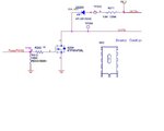
Alright this is the schematics of the driver.
untitled.JPG

I do not have a oscilloscope with me now and it would take a while to get one.

I will get it for testing if the problem is still unable to be solved.

Regards
 

The PWM signal from the MCU is able to be measured with a voltage of around 1V. But the output from the driver is 0V.

"output from the driver" means TP208/OUTB- or OUTB+ - OUTB-?

STP55NF06L is not specified for 3.3V Vgs, but should at least give some output current.
 

The output of the driver I mean OUTB+ and OUTB-
 

Quite a lot of code, but I don't notice configuration of PWM output pin.
 

oh right.

I missed out on the PWM config block of codes.

Its here:
Code:
void init_PWM()
{

    /* Set PWM Periods on PHASEx Registers */
    PHASE1  = 6000;
    SPHASE1 = 6000;
    PHASE2  = 6000;
    SPHASE2 = 6000;
    PHASE3  = 6000;
    SPHASE3 = pwmPeriod;  // period is 6000 -- Fosc/(Fpwm*prescaler)
    /* Set Duty Cycles */
    PDC1 = 200;
    SDC1 = 300;
    PDC2 = 400;
    SDC2 = 500;
    PDC3 = 600;
    SDC3 = 0;
    /* Set Dead Time Values */
    DTR1 = DTR2 = DTR3 = 0;
    ALTDTR1 = ALTDTR2 = ALTDTR3 = 0;
    /* Set PWM Mode to Independent */
    IOCON1 = IOCON2 = IOCON3 = 0xCC00;
    /* Set Independent Time Bases, Edge-Aligned Mode and Independent Duty Cycles */
    PWMCON1 = PWMCON2 = PWMCON3 = 0x0200;
    /* Configure Faults */
    FCLCON1 = FCLCON2 = FCLCON3 = 0x0003;
    /* 1:1 Prescaler */
    PTCON2 = 0x0000;
    /* Enable PWM Module */
    PTCON = 0x8000;
}

The PWM pin that I am using for this is channel 3-L. So the duty cycle is controlled by SDC3.

Regards
 

Status
Not open for further replies.

Similar threads

Part and Inventory Search

Welcome to EDABoard.com

Sponsor

Back
Top