Continue to Site

Welcome to EDAboard.com

Welcome to our site! EDAboard.com is an international Electronics Discussion Forum focused on EDA software, circuits, schematics, books, theory, papers, asic, pld, 8051, DSP, Network, RF, Analog Design, PCB, Service Manuals... and a whole lot more! To participate you need to register. Registration is free. Click here to register now.

Ceramic Capacitor (MLCC) Selection for automotive transient pulse

Status
Not open for further replies.

Gaurav_1806

Newbie level 4
Joined
Oct 19, 2013
Messages
7
Helped
0
Reputation
0
Reaction score
0
Trophy points
1
Activity points
51
Hello,

I am facing a field issue in on of my product, the input signal capacitor used for ESD protection gets burned out. The capacitor used is MLCC type, 100nF, 50V and 0603 package.

I think so the due to the high transient voltage on the input lines this capacitor may be getting degraded and over the period of time is getting burn out.

So, my confusion is to how to determine or calculate the maximum supported rated voltage will be need to sustain these automotive pulses.
 

Hi,

is it burnt caused by high voltage or by high currents?

Maybe a simple serial impedance helps (resistor, inductance, or both).


Klaus
 

Hello Klaus,

Thanks for the reply.

The burnt may be has caused due to high transient current which in case have ruptured the dielectric of the capacitor as the pulse peak voltage is well above the dielectric strength of the capacitor.

As as of now, I can't make changes to add a inductor or a resistor in series as the PCB is finalized and I have only chance to change the rated voltage of the capacitor i.e. to select a capacitor which will be having a greater rated voltage in the same package.

So, my confusion is to how to determine or calculate the maximum supported rated voltage will be need to sustain these automotive pulses.??
 

"Field issue" means the capacitor doesn't fail during tests rather than normal operation?

What kind of input signal is this?

MLCCs are known to withstand short pulses much higher than the rated voltage. So there must be massive or repeated overvoltage events in normal operation. Is this plausible?
 

Hello,

Yep !! You are absolutely right.

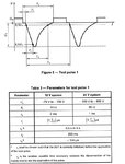
For your reference I am attaching pulse specification

Pulse 1.jpg
 

This is a specification for automotive power supply, not signal input. The problem is about power supply or signal input?

You are observing capacitor failure during ISO7637 tests or normal operation?
 

The capacitor is on the crank input signal, and due to the back emf of crank relay which may be coming directly across this capacitor.

As I am not able to find the exact reason for this failure so, i am considering the dielectric breakdown of the capacitor due to to this back emf of the crank relay.
 

Hi,

with high voltage pulses one could limit input current (series L, R) or limit voltage by using TVS or zener diode.

If the voltage waveform is given (without current limiting devices) the power to dissipate is very high, and also the resulting volltage is not limited.
S a combination of current limiting and voltage limiting should be a good solution.

But you said you can´t change layout, so I reall don´t have a solution for you.

Klaus
 

Hello Klaus,

Thanks for the reply.

Let me check from my side what else I can do..
 

You ought to understand two things. One is, what does it
take to rupture the dielectric on the bench, signal applied
to pin, voltage pulse height and width varying? Two, what
is the nature of the attached sensor's output open circuit,
short circuit and as-loaded?

Until you know these you can't even pick a voltage rating
(other than, "most I can get in the existing outline" which
at this capacitance and body size may not be much more
than presently).
 

Status
Not open for further replies.

Part and Inventory Search

Welcome to EDABoard.com

Sponsor

Back
Top