Continue to Site

Welcome to EDAboard.com

Welcome to our site! EDAboard.com is an international Electronics Discussion Forum focused on EDA software, circuits, schematics, books, theory, papers, asic, pld, 8051, DSP, Network, RF, Analog Design, PCB, Service Manuals... and a whole lot more! To participate you need to register. Registration is free. Click here to register now.

class B common emitter stage

Status
Not open for further replies.

julian403

Full Member level 5
Joined
Feb 28, 2014
Messages
254
Helped
1
Reputation
2
Reaction score
1
Trophy points
18
Location
Argentina
Activity points
2,105
It is possible to make a voltage amplifier ( common emitter stage ) style class B? , that is to say, with two transistors , one PNP and the other NPN . Where amplify each half cycle .

thanks.
 

If the NPN is at the positive (upper) side, then it will not be a voltage amplifier. Your incoming signal amplitude is the same (or less) as your output voltage.

Voltage gain is possible by putting the PNP at the upper side.

I have a Youtube video which portrays animated simulations of simple class B amplifiers. It examines several configurations.

https://www.youtube.com/watch?v=nLMC8j_8ys4
 
Thanks, i never saw that before. But it do not amplifies voltage. Why?

asdf.png

but that's SunnySkyguy amplifies current not voltage.

And yes, that transitors do not support that Vcc and Vee voltage but the simulator do not have 2SA1943
 
Last edited:


The circuit with the TIP31 and TIP32 transistors as common emitter has an average of nearly 70mA of base current for each transistor so they are conducting in class-A more current collector than their maximum allowed current and are getting much hotter than their maximum allowed dissipation, even when there is no signal.
 
Now I uses tips 142 and 147 with the same configuration and I have the same problem. Is there a book which talks about this topic? especialy this type of singular class B
 

Almost every audio amplifier uses complimentary (NPN and PNP) common-collector emitter-followers at the output, biased slightly into class-AB to eliminate class-B crossover distortion. Diodes or a transistor automatically adjust their bias so that temperature changes do not change their low idle current.

Your (crazy?) idea of using common-emitter output transistors causes them to be turned on hard conducting a LOT of current all the time and burning up.
 

Using a load of 8 or 800, it has a gain of 2. The source is Vcc=-Vee=25 volts. In what resistance depends gain ? Or which would be limitin gain?
 

Your (crazy?) idea of using common-emitter output transistors causes them to be turned on hard conducting a LOT of current all the time and burning up.
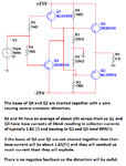
That would be also my comment about the circuit in post #4. Particularly it's pure class A (as long as the transistors withstand the high power dissipation), not class B.

As suggested by SunnySkyguy, you can have a complementary darlington class-B circuit with the final output transistors in common emitter configuration, if this fact is of specific relevance for you. I don't believe it is.

To ask more generally, what's the problem you want to solve?

A class B output stage needs a mechanism that makes either one or the other branch conduct at a time. In the well-known common collector class B stages, it's achieved automatically. There's no natural way to do the same in common emitter configuration, the said complementary darlington circuits have still a predriver in voltage follower (common collector) configuration.
 
asdf.png

That's the circuit, Vcc=-Vee=25V. And the load is 8 Ohms not 800, sorry.
 

Not enough stages to generate this much power gain.

You can't simply put in 60 dB gain and 1 emitter follower, not even close.

You have a lot to learn before you can design. Many violations.

Start by looking at impedance ratios of load to source working backwards. Then bias currents.
 

Your circuit has NOTHING to limit its EXTREMELY high current and heating. I explain a few of its problems here:
 

Attachments

  • horrible amplifier schematic.png
    horrible amplifier schematic.png
    25.1 KB · Views: 135

Status
Not open for further replies.

Similar threads

Part and Inventory Search

Welcome to EDABoard.com

Sponsor

Back
Top