bianchi77
Advanced Member level 4
- Joined
- Jun 11, 2009
- Messages
- 1,313
- Helped
- 21
- Reputation
- 44
- Reaction score
- 20
- Trophy points
- 1,318
- Location
- California
- Activity points
- 9,442
Reference Previous Thread:
https://www.edaboard.com/threads/276401/
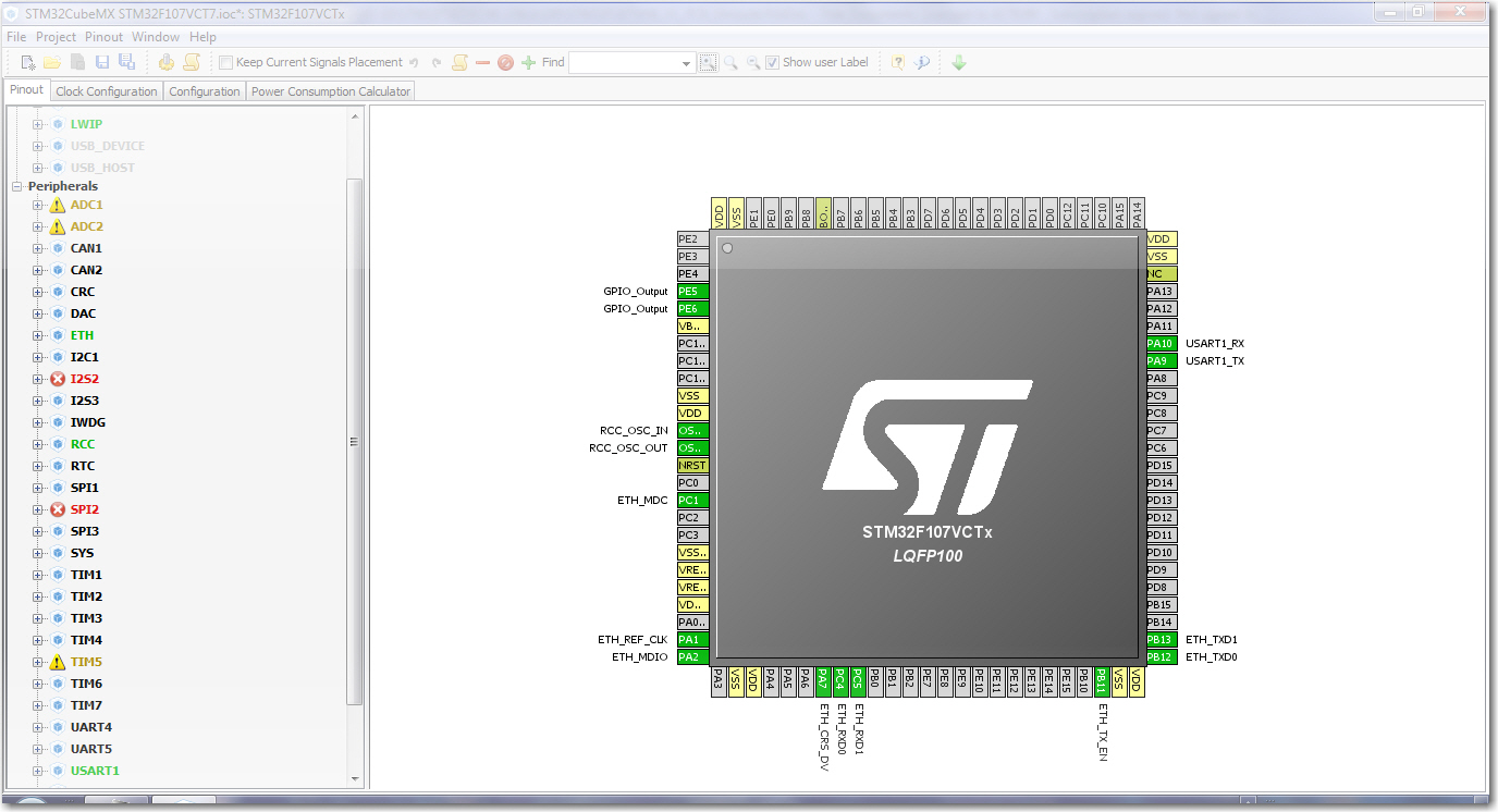
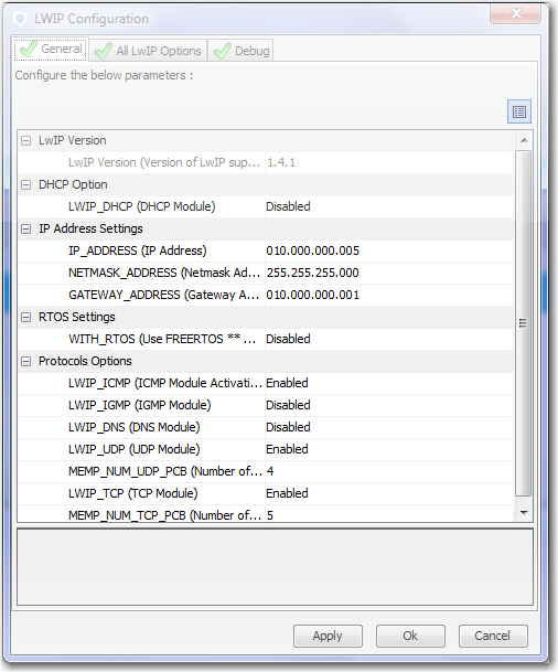
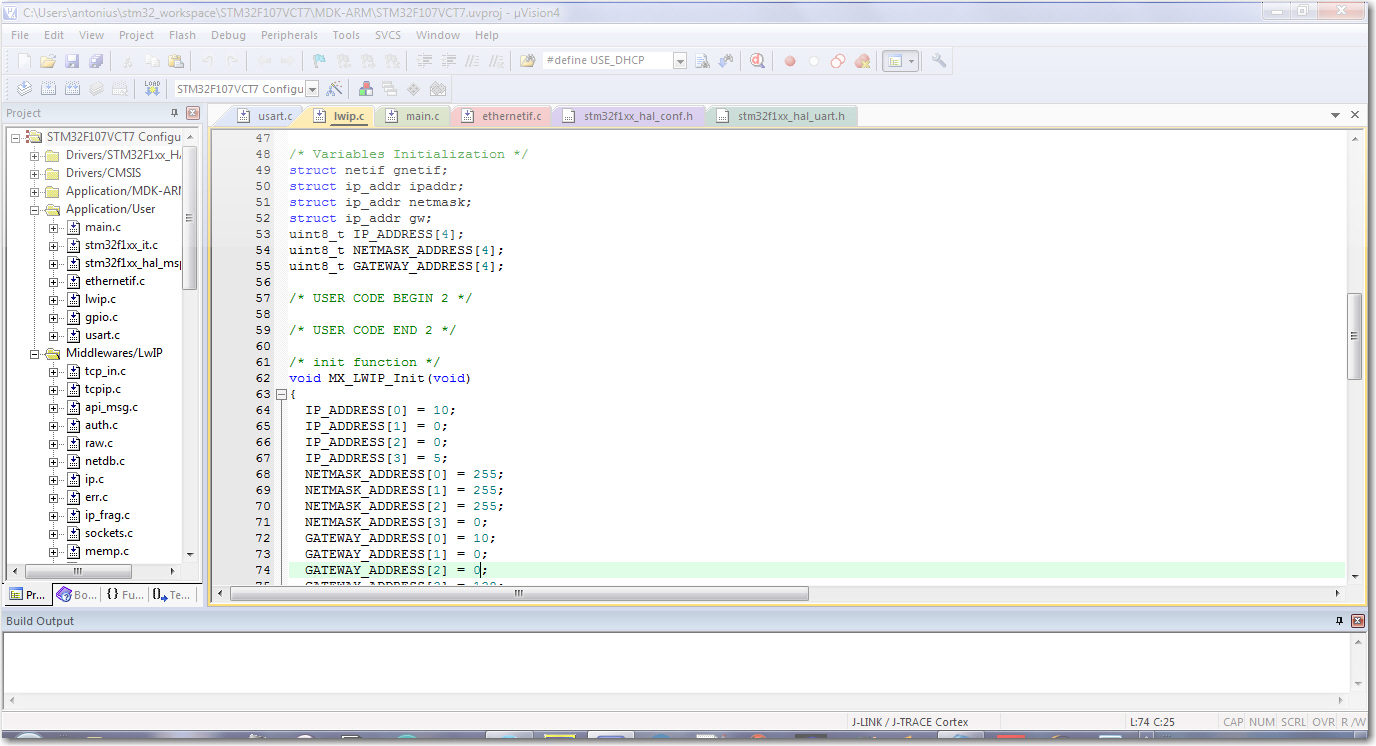
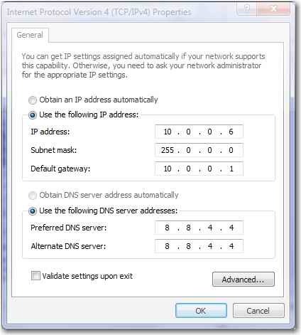
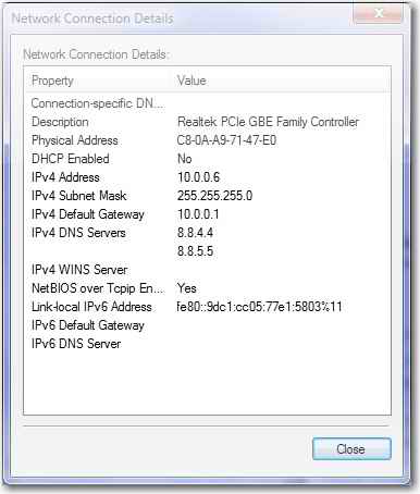
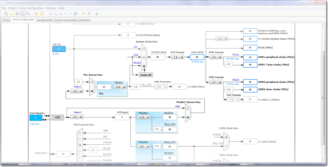
How can you set the IP address on LwIP ? I'm using STM32CubeMx and can not manage to ping my board yet ??
https://www.edaboard.com/threads/276401/
I have now done some logging and package sniffing and it seems like the webserver in the other end doesn't respond to the requests, rather than a problem with the RTOS and the lwIP stack.
This is the log:
Code:root@DD-WRT:/tmp/smbshare/tmp/ipkg# tcpdump host 192.168.0.136 tcpdump: verbose output suppressed, use -v or -vv for full protocol decode listening on br0, link-type EN10MB (Ethernet), capture size 96 bytes 21:06:16.755439 arp who-has 192.168.0.136 tell DD-WRT 21:06:17.749425 arp who-has 192.168.0.136 tell DD-WRT 21:06:18.749419 arp who-has 192.168.0.136 tell DD-WRT 21:06:19.009820 IP DD-WRT > 192.168.0.136: ICMP echo request, id 24829, seq 0, length 28 21:06:19.010268 IP DD-WRT.bootps > 192.168.0.136.bootpc: BOOTP/DHCP, Reply, length: 300 21:06:19.013484 IP DD-WRT.bootps > 192.168.0.136.bootpc: BOOTP/DHCP, Reply, length: 300 21:06:19.013816 arp who-has 192.168.0.136 tell 0.0.0.0 21:06:19.253541 arp who-has 192.168.0.136 tell 0.0.0.0 21:06:20.755843 arp who-has DD-WRT tell 192.168.0.136 21:06:20.756171 arp reply DD-WRT is-at 00:1c:10:36:55:d5 (oui Unknown) 21:06:20.756363 IP 192.168.0.136.49153 > api.theblast.dk.www: S 6509:6509(0) win 5840 <mss 1460> 21:06:23.505626 IP 192.168.0.136.49153 > api.theblast.dk.www: S 6509:6509(0) win 5840 <mss 1460> 21:06:26.505681 IP 192.168.0.136.49153 > api.theblast.dk.www: S 6509:6509(0) win 5840 <mss 1460> 21:06:29.505745 IP 192.168.0.136.49153 > api.theblast.dk.www: S 6509:6509(0) win 5840 <mss 1460> 21:06:32.505805 IP 192.168.0.136.49153 > api.theblast.dk.www: S 6509:6509(0) win 5840 <mss 1460> 21:06:35.505865 IP 192.168.0.136.49153 > api.theblast.dk.www: S 6509:6509(0) win 5840 <mss 1460> 21:06:38.505924 IP 192.168.0.136.49153 > api.theblast.dk.www: S 6509:6509(0) win 5840 <mss 1460> STM32 Debug: TIMEOUT 21:06:40.058179 IP 192.168.0.136.49154 > api.theblast.dk.www: S 6583:6583(0) win 5840 <mss 1460> 21:06:43.058028 IP 192.168.0.136.49154 > api.theblast.dk.www: S 6583:6583(0) win 5840 <mss 1460> 21:06:46.058071 IP 192.168.0.136.49154 > api.theblast.dk.www: S 6583:6583(0) win 5840 <mss 1460> 21:06:49.058133 IP 192.168.0.136.49154 > api.theblast.dk.www: S 6583:6583(0) win 5840 <mss 1460> 21:06:52.058188 IP 192.168.0.136.49154 > api.theblast.dk.www: S 6583:6583(0) win 5840 <mss 1460> 21:06:55.058256 IP 192.168.0.136.49154 > api.theblast.dk.www: S 6583:6583(0) win 5840 <mss 1460> 21:06:58.058307 IP 192.168.0.136.49154 > api.theblast.dk.www: S 6583:6583(0) win 5840 <mss 1460> STM32 Debug: TIMEOUT 21:06:59.565567 IP 192.168.0.136.49155 > api.theblast.dk.www: S 6731:6731(0) win 5840 <mss 1460> 21:06:59.587891 IP api.theblast.dk.www > 192.168.0.136.49155: S 2608560878:26085 60878(0) ack 6732 win 14600 <mss 1460> 21:06:59.588153 IP 192.168.0.136.49155 > api.theblast.dk.www: . ack 1 win 5840 21:06:59.589999 IP 192.168.0.136.49155 > api.theblast.dk.www: P 1:164(163) ack 1 win 5840 21:06:59.611974 IP api.theblast.dk.www > 192.168.0.136.49155: . ack 164 win 15544 21:06:59.677696 IP api.theblast.dk.www > 192.168.0.136.49155: P 1:221(220) ack 164 win 15544 21:06:59.678214 IP api.theblast.dk.www > 192.168.0.136.49155: F 221:221(0) ack 164 win 15544 21:06:59.678451 IP 192.168.0.136.49155 > api.theblast.dk.www: . ack 222 win 5619 21:06:59.729786 IP 192.168.0.136.49155 > api.theblast.dk.www: F 164:164(0) ack 222 win 5619 21:06:59.750428 IP api.theblast.dk.www > 192.168.0.136.49155: . ack 165 win 15544
In that case, as the server isn't responding properly, could it be something with the HTTP header?
The header I'm sending/using is:
GET / HTTP/1.1\r\nUser-Agent: Mozilla/4.0 (compatible; MSIE 6.0; Windows NT 5.1; SV1; .NET CLR 1.1.4322; .NET CLR 1.0.3705)\r\nHost: api.theblast.dk\r\n\r\n
Looking forward to your feedback.
Regards Thomas
How can you set the IP address on LwIP ? I'm using STM32CubeMx and can not manage to ping my board yet ??
Last edited by a moderator: