Continue to Site

Welcome to EDAboard.com

Welcome to our site! EDAboard.com is an international Electronics Discussion Forum focused on EDA software, circuits, schematics, books, theory, papers, asic, pld, 8051, DSP, Network, RF, Analog Design, PCB, Service Manuals... and a whole lot more! To participate you need to register. Registration is free. Click here to register now.

[SOLVED] Please help with VHDL UART packet sending

Status
Not open for further replies.

electrodarkness

Member level 1
Joined
May 2, 2010
Messages
39
Helped
0
Reputation
0
Reaction score
0
Trophy points
1,286
Location
Ganesti, Transylvania, Romania
Activity points
1,649
Hi everyone!
I'm designing a signal acquisition board with FPGA. For the FPGA -> PC communication I'm using UART protocol. The UART design is working, I've tested it with a simple echo loopback. Next I wanted to implement a protocol to send data : S D3 D2 D1 P \r \n, where Dx are decimal numbers. For testing this I've used an 8bit sine lookup table, but when sending the data, only S and \n are sent to the terminal. I checked my code numerous times, but I can't find what's wrong with it.

I've attached my VHDL files.
Any help would be really appreciated!
Thanks in advance!
 

Attachments

  • UART_FSM.rar
    3.5 KB · Views: 66

Have you got a testbench? that would be the easiest way to debug!
 

I briefly reviewed the TX-UART design. I'm missing a TX busy respectively idle output signal.

As far as I see, the TX strobe is immediately acknowledged. So how can you know when the UART is ready to receive the next character?

You could use the non-acknowledged strobe signal to pause the state machine, but yout don't in your present design. An explicite Tx ready signal would be however preferable.
 
Data transmission is started with uart_data_in_stb <= '1' and when the data is sent the uart_data_in_ack becomes '1', but you are right, I was only stopping the strobe bit when the UART was busy, the data counter was still working. Now I have a general idea, I will be back with the results.
Thanks so far!

- - - Updated - - -

And it works! Thanks FvM!
I cut the counter incrementation from the protocol part and pasted to the ack conditional branch and it works. One final question: Is there a more effective way to break down a number to digits than converting to BCD? Now I'm using BCD conversion + 0x30 to get the digit in ASCII format with 8bit number, but in the future I'm planning to work with 24bit numbers ( 32bit in BCD) .( I'm referring to something like n mod 10)?
 

Converting binary numer representation to decimal involves arithmetic operations. Using mod 10 in VHDL code usually infers a resource ineffective parallel divider. For a more effective conversion you can implement the Double Dabble algorithm https://en.wikipedia.org/wiki/Double_dabble in a sequential state machine.
 
Thanks again FvM! I will remain at the Double Dabble conversion since I will use at least one adaptive FIR, LSE and covariance calculation - hopefully all in real-time, so effectiveness is a key to this design.
 

I'm back again.
I managed to write a working UART, which sends data embedded in a protocol to an android device (via Bluetooth), and I can receive and plot the data ( only a sine from LUT).
Now I'm struggling with the SPI protocol. the SPI block contains a TX and RX shift register, a divider for SCK, and a finite state machine for controlling the block. I can successfully transmit data but the received data after exchange is always 0x00. I've tested the blocks separately and everything works fine.
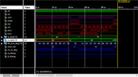
I've attached the SPI block VHDL files and the simulation picture.


I can't see what I'm doing wrong.
Thanks in advance.
 

Attachments

  • spi.rar
    5 KB · Views: 63

I see two issues with the code:
- clocking bit_num and shift registers by a divided clock and the state machine by the design input clock. This is likely to cause timing violations and unpredictable behaviour
- latching the rx shift register output by an asynchronous latch instead of a clocked register

In addition to using an asynchronous latch for parallel_out, you have an unnessecary reset of the shift register, which causes the code to fail reliably.
Code:
shift_in : process(shift_data, write_output)
  variable temp_reg : std_logic_vector(reg_length - 1 downto 0);
begin
  if write_output = '1' then
    parallel_out <= temp_reg;
    temp_reg := (others => '0');
  elsif falling_edge(shift_data) then
    temp_reg := serial_in & temp_reg(reg_length - 1 downto 1);
  end if;
end process shift_in;

A state-of-the-art synchronous design clocks all registers by the primary clock and implements the shift clock and strobe signals as clock enable.
 
Status
Not open for further replies.

Similar threads

Part and Inventory Search

Welcome to EDABoard.com

Sponsor

Back
Top