Continue to Site
Follow along with the video below to see how to install our site as a web app on your home screen.
Note: This feature may not be available in some browsers.


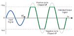
The clipping produced by the opamp creates harmonics. Will the harmonics mess up the results of the circuit?
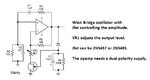
Why would the clipped voltage affect LVDT operation? I don't believe that this is the case. The answer might depend on the details of synchronous rectifier used as receiver. Level stabilisation would be wanted however, because the drive voltage acts as scaling factor for the displacement measurement.yes , can you tell how can I remove clipping, where I have to add Jfet in circuit, how to configure it.
Why, particularly? And what do you mean with an "isolater"?You need to isolate the circuit why don't you try with isolater.