Continue to Site

Welcome to EDAboard.com

Welcome to our site! EDAboard.com is an international Electronics Discussion Forum focused on EDA software, circuits, schematics, books, theory, papers, asic, pld, 8051, DSP, Network, RF, Analog Design, PCB, Service Manuals... and a whole lot more! To participate you need to register. Registration is free. Click here to register now.

problem with output swing

Status
Not open for further replies.

elli

Junior Member level 3
Joined
May 3, 2015
Messages
26
Helped
2
Reputation
4
Reaction score
1
Trophy points
3
Location
IRAN
Activity points
192
HI
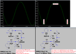
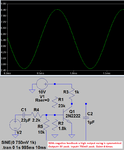
as i know the output resistor of the npn transistors cause the higher VCEsat if that bias current is high for example about to mA and if we used that as a output transistors that would make our swing lesser .
so what should i do in this case to have a symmetric swing in output ?
 

symmetric swing in output ?

Suppose your supply is 10V, and you want the midpoint (5V) to be the centerline for the output voltage swing. (I assume output is taken from the collector leg.)

Suppose your output resistor is 50 ohms. (I assume it is placed in the collector leg.) A 5V drop calculates to 100mA.

This is typical class A operation.

Therefore you want to bias the transistor so it adopts an average value of 50 ohms, over a cycle of operation. This will create an average drop of 5V. Calculate the bias on the transistor so it passes an average of 100mA.

Suppose the transistor has a gain of 100. Your average bias current will be 1mA.

For example, a bias current ranging between .9 and 1.1 mA will cause the transistor to pass between 90 and 110 mA. This will produce symmetrical voltage swings at the output.
 

ok thanks
my problem is that my power supply for my opamp is +-5 .
and i should get the 4 volt input and output all symmetric but my output just limited to -+3.5
and i think this must be because of the high current of the output transistors of my class ab
that should sink and source the 1k load !
and we know as our this much high current will cause about 2.2 volt for VCEsat as we assume the collectors resistor is about 500
 

A transistor with a high output level and no negative feedback has high distortion with an output that is not symmetrical:
 

Attachments

  • transistor without negative feedback.png
    transistor without negative feedback.png
    43.9 KB · Views: 54
  • transistor with negative feedback.png
    transistor with negative feedback.png
    22.4 KB · Views: 52

and i think this must be because of the high current of the output transistors of my class ab that should sink and source the 1k load !

Some common op amps can only sink or source a few mA. This calculates to an output resistance of several hundred ohms.

Therefore we must keep in mind whether the load tries to draw too much Amperes from the output.
 

Most opamps have emitter-follower darlington output transistors. Then they do not saturate, instead their emitter output follows the base with a 0.7V to 0.8V voltage drop. A darlington is two emitter-followers in series so of course each one produces a 1.5V voltage drop. Then with a plus and minus 5V supply the maximum output swing is plus and minus 3.5V.

Why do you talk about a 500 ohms collector resistor? A class-AB darlingtons emitter-followers output has no collector resistor.
 

Status
Not open for further replies.

Similar threads

Part and Inventory Search

Welcome to EDABoard.com

Sponsor

Back
Top