Continue to Site

Welcome to EDAboard.com

Welcome to our site! EDAboard.com is an international Electronics Discussion Forum focused on EDA software, circuits, schematics, books, theory, papers, asic, pld, 8051, DSP, Network, RF, Analog Design, PCB, Service Manuals... and a whole lot more! To participate you need to register. Registration is free. Click here to register now.

[SOLVED] First start with MPLAB ICD3 in Circuit debugger

Status
Not open for further replies.

KhaledOsmani

Full Member level 6
Joined
May 4, 2014
Messages
384
Helped
1
Reputation
2
Reaction score
1
Trophy points
18
Activity points
3,933
Hi

I've bought the MPLAB ICD3 from microchip.
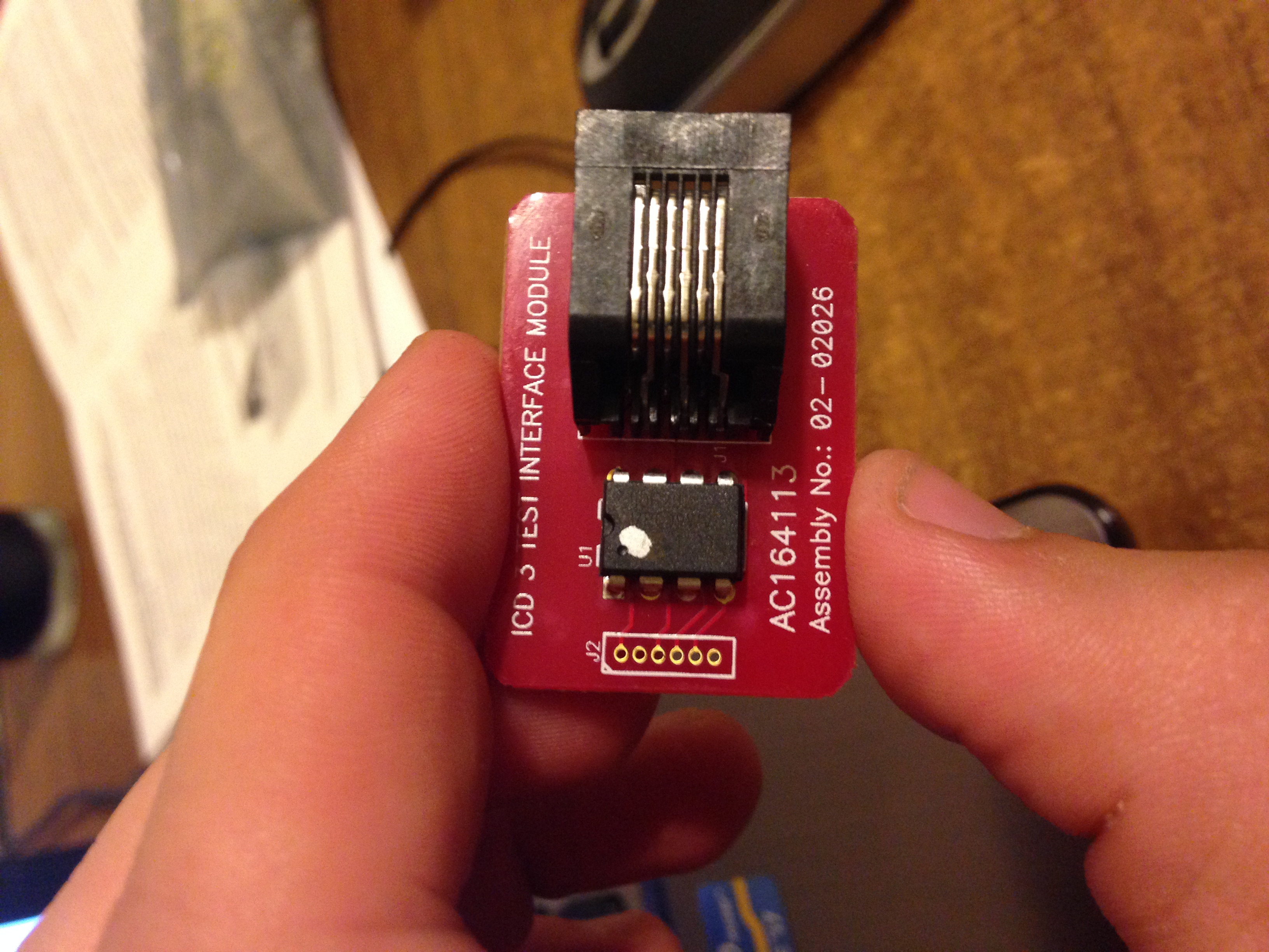
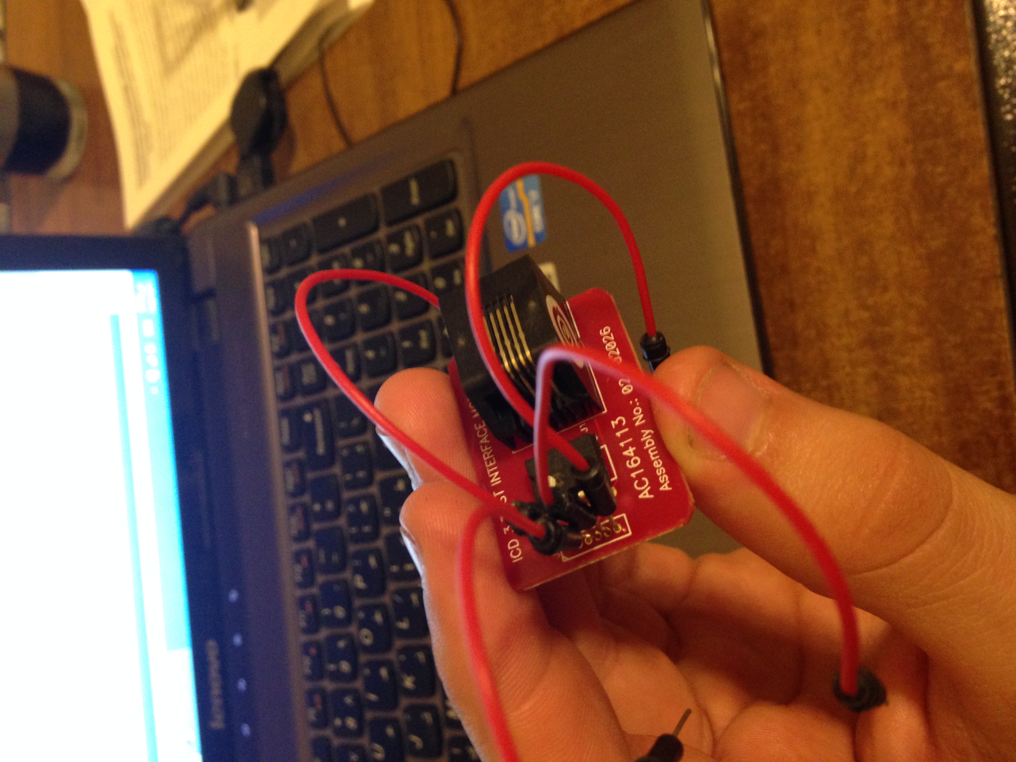
Attached is its photo.

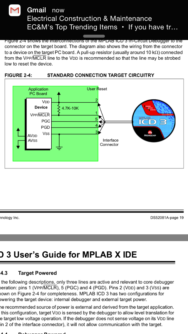
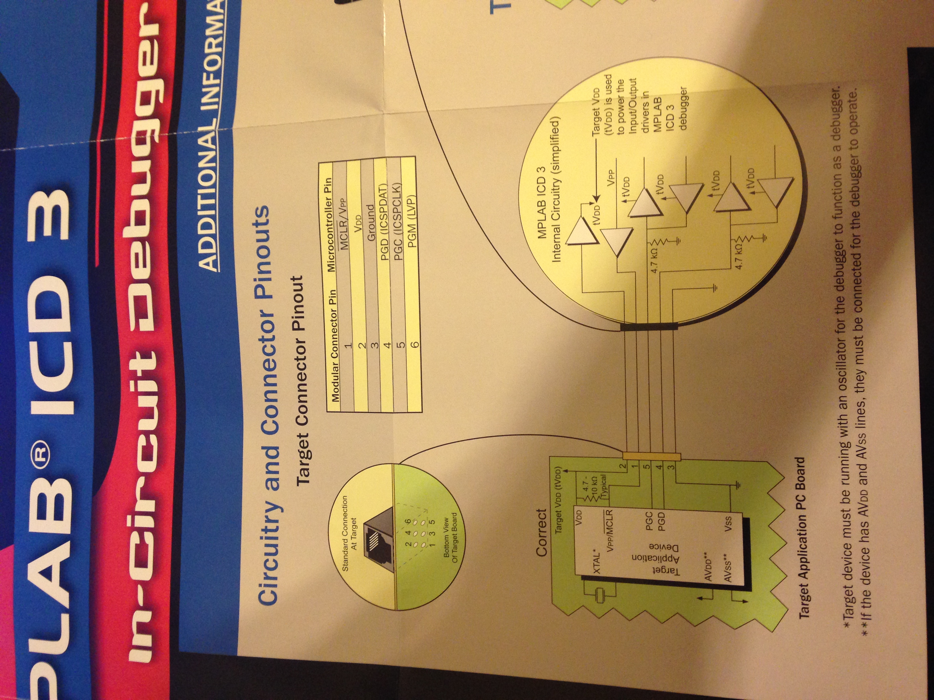
There must be a circuit to be created, and used with this gadget in order to program the PIC microcontroller.


How to set up such circuit, that in which the PIC can be "plugged" any schematic available?
 

Attachments

  • IMG_4318.JPG
    IMG_4318.JPG
    1.9 MB · Views: 142

attached is a circuit using a PIC24FJ64GB004 showing programing connector P3, reset button and output to LEDs
PIC24.jpg
 
@horace1

thanks man.


I found out that the gadget has an interface board with the datasheet concerning.

photo1 is the header circuit
photo2 is the concerning datasheet

this is what I will do, please state wether true or false:

1) connect the MPLAB ICD3 incircuit debugger with the USB interface to the laptop
2) install its driver correctly
3) I will attach wires to the photo1 by soldering iron, by taking into consideration each pinout according to its datasheet
4) PGC is portb.6 and PGD is portb.7
5) after the photo1 has soldered wires as it shows on photo3 i will put the PIC into a breadboard
6) connect both VDD to +5V and both Vss to GND
7) place the XTAL external oscillator of 20Mhz at pins 13 and 14 and place a 22pF from each terminal to GND
8) concerning photo3 that reveals the MPLAB ICD3 RJ-11 Jack pinout, I will connect the pins as follows:
pin2 to Vdd
pin1 to MCLR and place between MCLR and Vdd of the PIC a 10k resistor as: a pull-up resistor so that the line may be strobed low to reset the device
pin5 to PGC: PORTB.6
pin4 to PGD: PORTB.7
pin3 to Vss

as a summary the PIC should have its own power source of 5V, and must have its 20Mhz external crystal with its 22pF electrolytic caps branched in, the output of the MPLAB ICD3 goes to the photo1 and photo3 goes to the pic with connections as stated above.

anything else must be done thanks

photo1:

photo2:

photo3:

- - - Updated - - -

in the pic24.jpg that you had attached, the PIC input voltage source is of 3.3V similarly for the programming header, since in the photo the PIC you showed was PIC24F

I`m using PIC18F4520, and its input voltage must be of 5V.
the programming header would be connected to the PIC same voltage source of 5V or it must have a unique voltage source of 3,3V?

photo4:

what is AVdd and tVdd?
 

NOOOOOOOOOoooooooooo...............

Please stop! :bang:

The pain, the pain......


The gadget you are referring to is the ICD3 test module for troubleshooting the ICD3 if technical issues should arise, it essential tests a loop back condition. It has nothing to do with the actual programming/debugging interface to your circuit or design.

Please undo your modifications. You may need the poor little test module in the future.

All you need it to properly interface the ICD3 to your circuit or design is the cable and NOT the test module.

The ICD3 typically comes with a standard RJ12 to RJ12, straight through six conductor cable which is designed to plug directly into most of Microchip's development boards:

picdem_icd3[1].jpg

You can continue to use this cable with your circuits or designs when combined with an RJ12 Jack breakout board, like the following:

Title_medium[1].jpg

Or simply incorporate an RJ12 Jack or any other variety of interface into your design to directly accept the a cable from the ICD3:

programming_unit_mini[1].jpg

Or you can make your own programming cable with male pin headers which can plug directly into a breadboard:

73_1285852187[1].gif

Or any other manor of adapter cable variation you can imagine:

PIC-ICSP[1].jpg
 

Thank you bigdog,

I will try to design the cable with male pin headers as you stated.

How to identify the pins? If used closed loop beeper test with the multimeter, i can identify each male pin to which pin of the RJ12 jack, How to count the pins of the RJ12 jack, still from datasheet from left to right the pins goes from 1 to 6?

- - - Updated - - -

The male header pins must be connected after being identified, with photo2?

Do you have any concerns about photo2?

The PIC would have its own voltage source whereas both Vdd and both Vss to + and GND respectively? What difference is there between AVdd and AVss and tVdd and tVss?
 

I've attached both the ICD3 User Guide and Quick Reference Sheet, I've also posted the image of the ICD3 pinouts below:

ICD3Pinouts.JPG

Microchip mistakenly refers to the connector as an RJ-11, which is a six position, four conductor connector (6P4C), when in fact it is an RJ-12, which is a six position, six conductor connector (6P6C).

If you build your own cables, make sure you buy RJ-12s and matching six conductor cable, with the cable constructed straight through.

Looking into the RJ-12 jack of the ICD3 from left to right the pinouts are:

ICD3 RJ-12 left to right

Pin............Signal
1...............PGM
2...............PGC
3...............PGD
4...............GND
5...............VDD
6...............MCLR/VPP

If you were to install an RJ-12 on your design, keeping in mind the cable is a straight through configuration, the connections would be reversed looking into the RJ-12 jack from left to right:

Target Design RJ-12 left to right
Pin............Signal
1...............MCLR/VPP
2...............VDD
3...............GND
4...............PGD
5...............PGC
6...............PGM

The pinouts above should give you the required information for constructing your own custom cables.

Please read the attached user guide, as it contains valuable information.

- - - Updated - - -

The male header pins must be connected after being identified, with photo2?

Yes, include a header or jack on your target design which provides these connections to the ICD3.

Do you have any concerns about photo2?

None, it appears to be correct. Keep in mind, as the cable is straight through, its pinout is reversed at the target in relation to looking into the RJ-12 of the ICD3. Review the second pinout table contained in my previous post.

The PIC would have its own voltage source whereas both Vdd and both Vss to + and GND respectively?

Yes, the ICD3 must share a common GND, it can be configured to either provide the target operating voltage or allow the target to provide its own operating voltage, in either case, the ICD3 must sense the appropriate Vdd levels are present before it will proceed in programming/debugging the device, therefore the Vdd of the target must be connected to the Vdd signal line of the ICD3 for proper operation.

The ICD3 will generate the correct programming voltage specific to the target on the MCLR/VPP pin.

The internal debugger power is limited in two aspects: (1) the voltage range is not as
wide (3-5V); and (2) the amount of current it can supply is limited to 100 mA. This may
be of benefit for very small applications that have the device VDD separated from the
rest of the application circuit for independent programming, but is not recommended for
general usage as it imposes more current demands from the USB power system
derived from the PC.

Be aware that the target VDD is sensed by the debugger to allow level translation for
target low-voltage operation. If the debugger does not sense voltage on its VDD line (pin
2 of the interface connector), it will not allow communication with the target.

What difference is there between AVdd and AVss and tVdd and tVss?

While the reference to tVdd and tVss is unclear, the reference to the AVdd and AVss, if present on the target, is in regards to the fact all Vdd, Vss, AVdd and AVss should be connected to their appropriate levels for the target device operate correctly, regardless of whether or not it is being programmed, debugged or operated normally.

In other words, all power related connections should be made on the target device for it to operate as expected, before attempting to program or debug the device.

Not all devices have the AVDD and AVSS lines, but if they are present on the target
device, all must be connected to the appropriate levels in order for the debugger to
operate.

In general, it is recommended that all VDD/AVDD and VSS/AVSS lines be connected to
the appropriate levels. Also, devices with a VCAP line (PIC18FXXJ for example) should
be connected to the appropriate capacitor or level.


BigDog
 

Attachments

  • 51766B.pdf
    1.9 MB · Views: 131
  • DS-51765C.pdf
    188.3 KB · Views: 119
@BigDog

I have the RJ12 to RJ12 straight through six conductor cable from microchip.

I found this connector on Ebay:
https://www.ebay.com/itm/RJ11-RJ12-...-Board-Terminal-Block-Connector-/371278113106

Do you have any link for a development tool as you say, so that the whole target board is constructed, and have that RJ12 connecter, and also power source for pic, and everything, I just plug the cable in it, after putting in the PIC, and program, without the need to construct the PIC programming circuit my self, by empowering it, placing an oscillator etc..?

- - - Updated - - -

maybe this:
https://www.microchipdirect.com/ProductSearch.aspx?Keywords=AC162049
 

@BigDog

I have the RJ12 to RJ12 straight through six conductor cable from microchip.

I found this connector on Ebay:
https://www.ebay.com/itm/RJ11-RJ12-...-Board-Terminal-Block-Connector-/371278113106

Perfect. It should allow you to access the required signal lines if breadboarding your design for example. I would recommend, keeping all ICSP lines as short as possible, particularly those which are emanate from such a breakout board.

I've used breakout boards similar to the following:

RJ11 Breakout Board

Both our examples have connections to solder a male pin header on the underside, which can be then plugged into the breadboard, alleviating the need to run individual connections from the screw terminal connectors.

Do you have any link for a development tool as you say, so that the whole target board is constructed, and have that RJ12 connecter, and also power source for pic, and everything, I just plug the cable in it, after putting in the PIC, and program, without the need to construct the PIC programming circuit my self, by empowering it, placing an oscillator etc..?

Microchip offers numerous development boards which have a built-in RJ-12 jack for ICSP, allowing for the direct connection of the ICD3.

I have several of both the following:

PIC18 Explorer Board

Explorer 16 Development Board with 100-pin PIM

As well as many other Microchip development boards.

Both offer plug-in modules (PIM) to easily change to target microcontroller and either Pictail or Pictail Plus bus connectors to plug-in additional development modules or allow easy access to all the available pins of the microcontroller.

An often underused resource, is the freely available schematics and board designs available for most of Microchip's development boards.

Keep an eye out on eBay, I often see the above development boards available used at great savings.

Also, Microchip offers most of their development tools at discounts to students and offer monthly specials on several of their development tools:

**broken link removed**

Save up to 50% with our monthly deals on Microchip Development Tools

BigDog

- - - Updated - - -


I'm NOT a big believer in using these types of programming sockets for the development phase. Repeatedly removing and replugging a microcontroller is one of the easiest ways to damage it.

For small scale production, that is another matter, but not for the design phase of a project.

It would be more prudent to include into your PCB design six inline pads for a pin header to accommodate the ICSP lines, actually five for that matter as the PGM line is only for low voltage programming and not commonly used.

Also, remember one of the benefits of the ICD3 is the ability to debug your design while in circuit, which is a very powerful feature.

BigDog
 
@BigDog

Ok I see.
Thanks man.
I`m just too frustrated that I will need to wait for another month to get the dev tool :('

I will get the Jack breakout board, and at the same time, I will get a development tool.

Do you recommend the Part Number AC162049 - Universal Programming Module for MPLAB ICD 2 & ICD 3 to buy from above all other dev tools you stated? it is the cheapest one: https://www.microchipdirect.com/ProductSearch.aspx?Keywords=AC162049

Is it plug and play only? plug the PIC program it by MPLAB and that's it? Since I will be buying and waiting, do you advise me to buy anything that I might use in the future?

- - - Updated - - -

- - - Updated - - -

I'm NOT a big believer in using these types of programming sockets for the development phase. Repeatedly removing and replugging a microcontroller is one of the easiest ways to damage it.

For small scale production, that is another matter, but not for the design phase of a project.

It is for a small scale production, but in such prototypes, Do I have to power up the pic, and add an 20Mhz oscillator? does it have an RJ12 socket?
 
Last edited:

Do you recommend the Part Number AC162049 - Universal Programming Module for MPLAB ICD 2 & ICD 3 to buy from above all other dev tools you stated? it is the cheapest one: https://www.microchipdirect.com/ProductSearch.aspx?Keywords=AC162049

No, I do not recommend it, as per my previous post. And frankly, you do not need it, it's a waste of money.

Surely, there is a place nearby which sells telephone cable and RJ-12 connectors, simply make an RJ-12 to male pin or female header cable.

You can make an RJ-12 to male pin header cable which can then be plugged directly into a breadboard in a matter of minutes.

Save the money and buy a new or used PIC18 Explorer, you'll be happy you did. I use the PIC18 Explorers I own, quite frequently when beginning a new design phase.

Is it plug and play only? plug the PIC program it by MPLAB and that's it? Since I will be buying and waiting, do you advise me to buy anything that I might use in the future?

Plug n Play? Well, you simply connect your target design circuit to the ICD3, compile your code using the MPLAB or MPLABX IDE, then download and debug your code. You can then set breakpoints, step through your code, watch various values, variables, etc, within the debugger windows of the MPLAB/MPLABX IDE.

Programming your device is almost secondary compared to the debugging capabilities of the ICD3 when in the design phase of your project.

Microchip offers an RJ-12 to ICSP pin header adapter, which is commonly referred to as a PICkit interface adapter:

RJ-11 to ICSP Adapter

However, it is essentially the same as the two RJ-12 breakout boards we previously discussed.

If you purchase an RJ-12 breakout board and possibly a Microchip development board for a microcontroller of your choice, I do not foresee any need for additional items at this time.

In the meantime, run down to the hardware store and pickup some telephone 6P6C cable and a bag of RJ-12 connectors, along with some inline pin headers and make an adapter cable, you can be up and running in minutes.

You could also make an RJ-12 to minigrabber cable if you have some minigrabbers laying around which could then be connected directly to any existing designs without an ICSP port or RJ-12 jack.


BigDog

- - - Updated - - -

It is for a small scale production, but in such prototypes, Do I have to power up the pic, and add an 20Mhz oscillator? does it have an RJ12 socket?

In that case, such an adapter may come in handy if repeated programming of small numbers of the same microcontroller is required.

The ICD3 can provide power to the device being programmed, adjustable in the 3V to 5V range if I remember correctly.

An oscillator is not required for PIC programming as the required clock is provided by the PGC line.

Yes, there appears to be an RJ-12 jack in the upper left corner of the device as shown in the photo:

AC162049[1].jpg

Microchip also offer a more versatile adapter which offers a wider range of operating voltages:

Part Number AC162049-2 - Universal Programming Module 2

Both adapters come with jumpers to ensure you properly connect the ICSP lines to the correct pins of the specific target microcontroller, as well as ensure all Vdd, Vss, AVdd and AVss pins are at their proper voltage levels.

However, if you are only programming a small handful of devices, you could just as easily setup a small breadboard to program them, you could even include a ZIF socket on the breadboard for easy of insertion and removal of the target device. Such as setup might provide less expensive while more versatile in the long run for small quantity production runs.

BigDog
 

Surely, there is a place nearby which sells telephone cable and RJ-12 connectors, simply make an RJ-12 to male pin or female header cable.

You can make an RJ-12 to male pin header cable which can then be plugged directly into a breadboard in a matter of minutes.


In the meantime, run down to the hardware store and pickup some telephone 6P6C cable and a bag of RJ-12 connectors, along with some inline pin headers and make an adapter cable, you can be up and running in minutes.

You could also make an RJ-12 to minigrabber cable if you have some minigrabbers laying around which could then be connected directly to any existing designs without an ICSP port or RJ-12 jack.


BigDog


Here, no one has the 6P6C cables, nor RJ-12.

You already stated how to make male/female pins from 6P6C Cables, as one side refers to the RJ-12 and the other side refers to six cable pinouts, that I can plug in the breadboard, and refer to photo2 and make the dev tool my self, it is the simplest and most great idea, but no one here deals with such stuff, they only have RJ-11 (used for telephone) or RJ-45 (used for LAN cables...)

Finally I will buy this: https://www.ebay.com/itm/RJ11-RJ12-...-Board-Terminal-Block-Connector-/371278113106 and make my own dev circuit same as photo2.

As for the programming module, do you have other option than the PIC18 Explorer, since it needs its own driver installation, and has its own way of programming and burning the code. I hated it ever since the Lab days. Do you have other tools, with 3M connectors that allows of inserting/removing PIC, and has RJ-12 to communicate with the ICD3?

- - - Updated - - -

Microchip also offer a more versatile adapter which offers a wider range of operating voltages:

Part Number AC162049-2 - Universal Programming Module 2

Both adapters come with jumpers to ensure you properly connect the ICSP lines to the correct pins of the specific target microcontroller, as well as ensure all Vdd, Vss, AVdd and AVss pins are at their proper voltage levels.


BigDog

does this one has a ZIF socket? Why isn't there any PDF datasheet for it, its picture is too small
 

does this one has a ZIF socket? Why isn't there any PDF datasheet for it, its picture is too small

They both have ZIF sockets and RJ-12 jacks as shown in the following, click to enlarge photos:

F7650683-01[1].jpg

The AC162049-2 above appears to have an ICSP header as well.

Microchip-AC162049[1].jpg

Here, no one has the 6P6C cables, nor RJ-12.

You already stated how to make male/female pins from 6P6C Cables, as one side refers to the RJ-12 and the other side refers to six cable pinouts, that I can plug in the breadboard, and refer to photo2 and make the dev tool my self, it is the simplest and most great idea, but no one here deals with such stuff, they only have RJ-11 (used for telephone) or RJ-45 (used for LAN cables...)

I find it hard to believe, in the entire country of Lebanon, no one stocks any RJ-12 or flat 6P6C telephone cable, as both are widely used in the telephony field, however if that is the case, you might as well order a spool of flat 6P6C cable and a bag of RJ-12 jacks and sockets from online as well as a nice supply of male and female inline headers, as they are probably hard to obtain there as well. :lol:

As for the programming module, do you have other option than the PIC18 Explorer, since it needs its own driver installation, and has its own way of programming and burning the code. I hated it ever since the Lab days. Do you have other tools, with 3M connectors that allows of inserting/removing PIC, and has RJ-12 to communicate with the ICD3?

The PIC18 Explorer does not require any special driver installation, you can simply choose which onboard features you wish to utilize and include the appropriate code to drive them within your application. If you desire to use the onboard LCD fine, if not don't.

However, there are numerous development boards from third parties available online with either the ICSP RJ-12 jack or a PICkit style pin header interface, both use the same signal lines, just in a different form factor. You should probably make a RJ-12 to ICSP female header socket (PICkit interface) adapter, it may come in handy.

If you search on eBay there are a number of Chinese manufacturers which offer Microchip based development boards, perhaps they have something more suited to your needs.

BigDog
 
@BigDog

Hi,

I've bought img1.JPEG:


I've connected jumper wires to it img2.JPEG and tested that all connections are not Open-conductor/Short-circuit faulted:


I've connected the ZIF socket on it the PIC, also an LM7805 with 0.33uF and 0.1uF on its I/O to the breadboard img3.JPEG:


I'm waiting your reply to do img4.JPEG but there are few notes that I would like to present:


1) I will branch the output of the LM7805 of 5 volts as: +5V to both Vdd on pins 11 and 32 (PIC18F4520) and 0V to both Vss on pins 12 and 31
2) If you notice in img4.JPEG there exists an XTAL seems that must be connected, contrarily to what you have told me about pins PGC/PGD that they would play the role of the oscillator, so I connect a 20Mhz external osc or not?
3) I will branch a 10K between pin 1 (MCLR) and Vdd of the PIC
4) In the logo that I got from microchip, and under the section that you told me that they mistakenly wrote RJ-11 instead of RJ-12, the pins goes from 1 to 6 from left to right, this is the for the input of the RJ-12 Jack break board? I`m still confused about the division of the lines, since its straight through, and reversed at the other side, I still cannot know each pin to what it corresponds, the worst case is that I can flip the order.
5) When the hardware is done, I will burn a code .hex into the PIC using MPLAB IDE V8.88 as I tried it with the test module and it said ICD3 test succeeded but after than gave me an error that I should connect the target device.
 

BigDog BigDog
It worked it worked

I programed the hex code into it and it suceeded


Thanks much
 

Congrats!

Have you attempted to utilize the ICD3 as a debugger yet?

If not, you should give it a try as well. Practice setting breakpoints, single stepping through the code, add and watch specific variable contents, etc.

The second attached PDF in the following reply contains the ICD3 debugger manual and should provide you plenty of examples of how to use its features.

https://www.edaboard.com/threads/340046/#post1450705


BigDog
 

Thank you for all your vociferous efforts and sinplified explanations
 

Status
Not open for further replies.

Similar threads

Part and Inventory Search

Welcome to EDABoard.com

Sponsor

Back
Top