Continue to Site

Welcome to EDAboard.com

Welcome to our site! EDAboard.com is an international Electronics Discussion Forum focused on EDA software, circuits, schematics, books, theory, papers, asic, pld, 8051, DSP, Network, RF, Analog Design, PCB, Service Manuals... and a whole lot more! To participate you need to register. Registration is free. Click here to register now.

220v DC to 220v AC Transformerless invertor circuit diagram required

Status
Not open for further replies.

rana_tdm

Newbie level 4
Joined
Jun 14, 2015
Messages
5
Helped
1
Reputation
2
Reaction score
0
Trophy points
1
Activity points
47
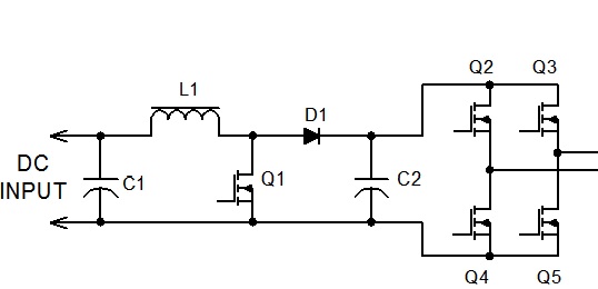
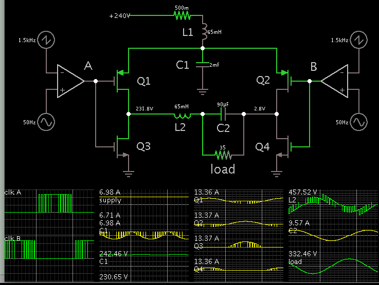
I have a battery bank of 20 Batteries 12v 7 Amps. I want to design a Transformerless 220v Dc to 220v AC invertor. I have searched alot but unable to find such circuit on internet. Please provide a circuit with short corcuit and overload protection.
 

combine a boost chopper and a H-bridge inverter.
 

Thanks for ur response kappa_am but do you have a diagram for this...what kind of boost chopper and waht do u mean by H bridge inverter...inverters being used here are mostly H bridge 12v DC to 220v AC... i dont want to use any kind of tranformer...and unable to find a circuit diagram of just an H bridge with 220v or more Dc input and 220v AC output with overload protection
 

I have attached the circuit that I think is suitable for your purpose. I do not have the control section. you can google it you'll have many circuits which can easily adapt to your application.
there is no inverter with capability to convert 12V DC to 220V AC because the inverters operate in buck mode and the DC link has to be larger than peak of AC output.
commercially available converters known as inverter are combination of a converter working in boost mode and a inverter. Same as the circuit I have mentioned.
 
This is a simple simulation showing (theoretically) how you might run 240 VDC through a full H-bridge to obtain AC square waves...

Then boost it while filtering it through an LC 2nd order filter...

Resulting in 230 VAC sine to a 7A load. The sine peaks are 330 V.


L1 and C1 create a filter which allows you to draw smooth 7A continuously from the battery bank.

The carrier frequency shown is 1500 Hz, to make the PWM waveform easy to see. However you can make it a higher frequency, and adjust coil and capacitor values to suit.

The mosfets are biased with unrealistic volt levels. A real control circuit will need to be designed to provide safe biasing for the mosfets.
 
Status
Not open for further replies.

Similar threads

Part and Inventory Search

Welcome to EDABoard.com

Sponsor

Back
Top