Continue to Site

Welcome to EDAboard.com

Welcome to our site! EDAboard.com is an international Electronics Discussion Forum focused on EDA software, circuits, schematics, books, theory, papers, asic, pld, 8051, DSP, Network, RF, Analog Design, PCB, Service Manuals... and a whole lot more! To participate you need to register. Registration is free. Click here to register now.

Current Sensor Circuit Calibration

Status
Not open for further replies.

oldev

Newbie level 3
Joined
Jan 20, 2015
Messages
3
Helped
0
Reputation
0
Reaction score
0
Trophy points
1
Activity points
44
After having to replace a few components in a system containing the current measurement circuit shown below, I have not been able to find a sensible and repeatable way of calibrating the circuit.

One approach was to set the input current to 1A, and turn R1 and R7 until the system output read 1A.
Then when changing the input to 10A, the system output is incorrect.
If I start by setting the input current to 10A and turn R1 and R7 until the system output reads 10A, then when I change the input to 1A, the system output is incorrect.

Another approach was to first, with input current set to 0A and with R1 to R4 junction shorted to 0V, turn R7 until the system output read 0A, and then attempt the above, yet only adjusting R1. This also produces incorrect results.

Any comments or suggestions which may shed light on a sensible and repeatable approach towards the calibration of this circuit will be appreciated.

8HmFf9DiveGH0AAAAASUVORK5CYII=
 

Hi,

I can't find your circuit...

It's better to tell us the value than writing "the system output is incorrect.".

What measurement tools do you use?

Klaus
 

Hi Klaus,

Thank you for your response.

Apologies, I have not previously used edaboard, and it appeared during the thread creation that the circuit was visible.

I have attached a jpg file containing the circuit image.

I respect the fact that a particular value is more useful than "the system output is incorrect" , however this circuit is part of a somewhat more elborate device, and the output of this circuit feeds and ADC, MCU, etc. In addition, I have repeated what I have described many times, and each time the output is different from the previous. I therefore believe that I am missing something important, most likely due to lack of knowledge and experience in the analog space.

My current source is a current-limiting bench PSU capable of 15A at 30V. The circuit output feeds an and MCU-based ADC.

Ol

Current Sense.JPG
 

In a first order, one would expect that the circuit can be adjusted with R7 for zero output first and then with R1 for full scale.

Varying R1 or even shorting the "R1 to R4 junction" to ground can however affect the zero adjustment if the OP has a high input current. What's the OP type?
 

    V

    Points: 2
    Helpful Answer Positive Rating
All linear circuits are calibrated using the offset and slope method.

In your case, adjust R7 first for zero offset with zero applied current.
Then, with a KNOWN CURRENT VALUE applied, adjust R1 to read that same value. That current value should be as close to full range as possible.

You may want to tweak R7 and R1 again. That's it!
If it isn't working, then you have something wrong.

I'm also going to ask, what type of opamp are you using? Is it a 741?
 

    V

    Points: 2
    Helpful Answer Positive Rating
Hi,

You need very good layout. Four wiring RSense. RSense has no name...don't use a copper trace as RSense.
What is the expected current range?
Is the current DC or is it pulsed? What frequency?

1A at 0.001Ohms gives 1mV. Measuring in this range you may expect thermocouple effects as error. Try to keep everything at equal temperature. Short wires, small area. Because of thermocouple errors I'd rather put the pot in the feedback path
Opamp type is essential.

Klaus
 

    V

    Points: 2
    Helpful Answer Positive Rating
Normally current shunts are in the range of 50 mV full scale for reliable readings. Copper shunt track width must be << main power tracks e.g. 30 mil. For 1A full scale, using a length of 0.5" 10 mil track of 1 oz Cu. gets you 49 mOhms within 10% or so your null offset and gain adjust can reach full scale with a gain of 100 to 5V or whatever.

Use a track caclulator and of course an Op Amp that senses to ground if single supply.

https://circuitcalculator.com/wordpress/2006/01/24/trace-resistance-calculator

If a voltage regulator is used, the shunt can be on the high or low side with a differential amp and voltage feedback outside the shunt to the regulator, so that load regulation is not degraded by adding 50 mOHm source impedance.

WIth a 50mV shunt designed for any current, calibration becomes trivial.
 

    V

    Points: 2
    Helpful Answer Positive Rating
res.jpg

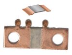
Thank you for all your replies. I have added an image containing pics which are very similar to what I have seen used on this circuit. The opamp used is an OP07. I am told that the device, which is part of a DC battery management system, can handle up to 50A.

FvM, Schmitt Trigger, your suggestion regarding first nulling the output offset prior to attempting any calibration is what I initially attempted, as described below.

With zero input, I connected the R1..R4 junction to 0V, and turned R7 while measuring the opamp output with a 6-digit bench multimeter.

Once the output was adjusted to as low as I could get it (units of uV), I then disconnected the R1..R4 junction from 0V, set 1A at the input using a current-limiting PSU, and turned R1 until the system display output 1.0A

I then set 10A at the input, and as mentioned previously, do not see the expected 10.0A on the system output. The output also varies between calibration attempts on different systems under repair.

I made the assumption that I either missed something technical due to my not having previously had to "calibrate" such sensitive sensing circuitry, and / or that I have missed some faulty component/s. My request for comment/s here is an attempt to obtain more clarity than I have otherwise been able to find.

Ol
 

Instead of shorting anything inside your circuit, you should care that the measured current is actually zero when adjusting zero scale.

One reason is that your measurement circuit most likely involves voltage drops due to lack of a true 4-wire ("kelvin") shunt configuration. If you short R1-R4, you still measure these voltage drops.

The error can be considerably reduced by connecting R3 directly to the shunt low-side.

OP07 is good, there shouldn't be relevant bias current induced errors.
 
  • Like
Reactions: oldev

    oldev

    Points: 2
    Helpful Answer Positive Rating
Capture.PNG

Here is a snip of a board layout I made many years ago, for a constant current load. Good for 10 amps continuous (100 mV), 12 amps momentary (120 mV).

Check out the 4-terminal resistor R10 layout and how close it is to the input terminals.
I used an OPA37 for the sense amp.
By using 1% tolerance sense resistor, and 0.5% for the gain resistors, I was able to calibrate in software, no pots required, by using the method I described above.
 
  • Like
Reactions: oldev

    oldev

    Points: 2
    Helpful Answer Positive Rating
Status
Not open for further replies.

Part and Inventory Search

Welcome to EDABoard.com

Sponsor

Back
Top