Continue to Site

Welcome to EDAboard.com

Welcome to our site! EDAboard.com is an international Electronics Discussion Forum focused on EDA software, circuits, schematics, books, theory, papers, asic, pld, 8051, DSP, Network, RF, Analog Design, PCB, Service Manuals... and a whole lot more! To participate you need to register. Registration is free. Click here to register now.

[SOLVED] Pulse LF signal antenna switching circuit for clip ring down

Status
Not open for further replies.

Robert T

Member level 1
Joined
Dec 21, 2011
Messages
40
Helped
3
Reputation
6
Reaction score
3
Trophy points
1,288
Activity points
1,655
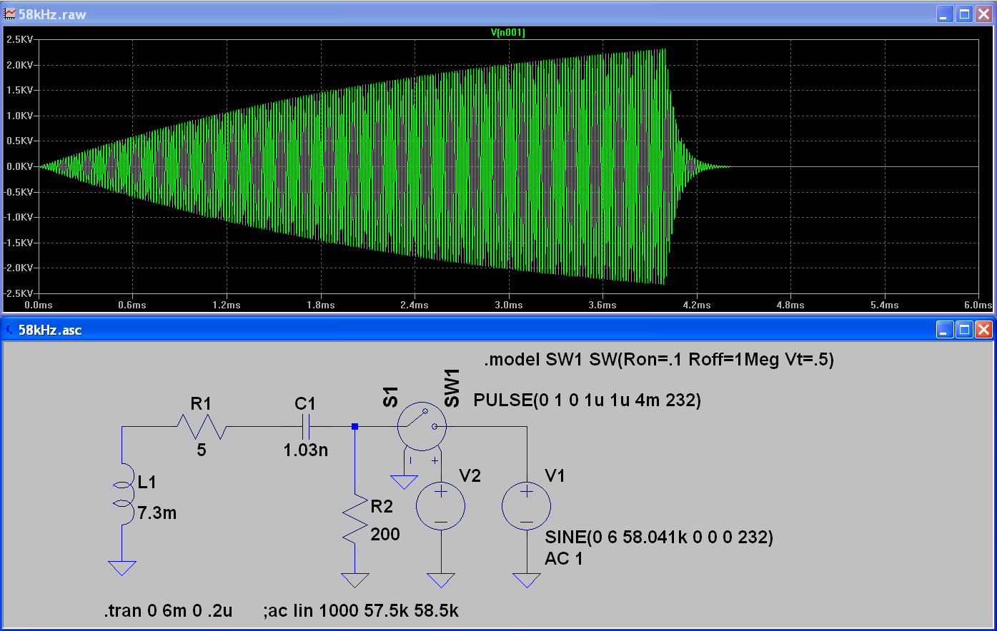
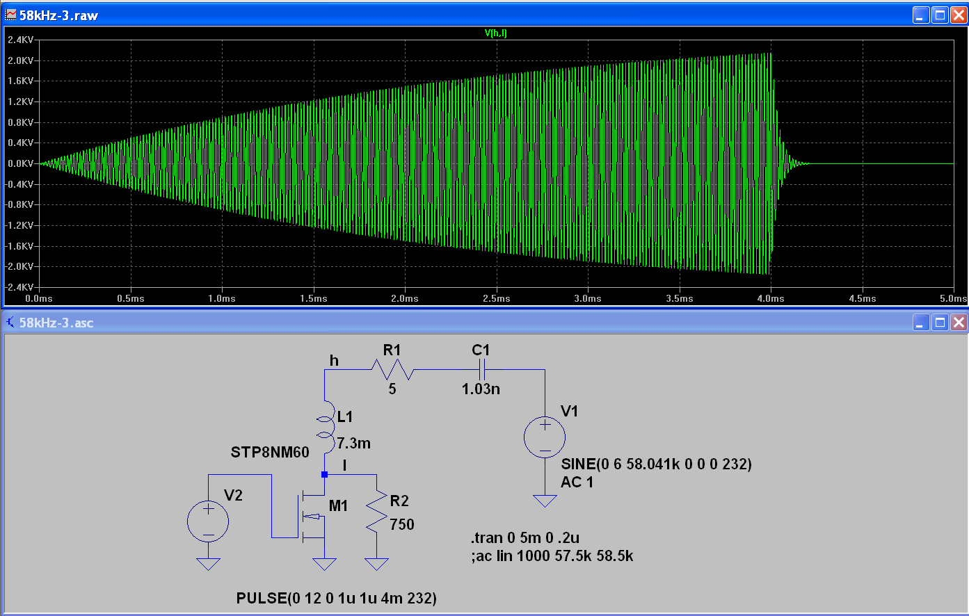
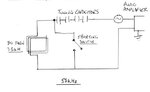
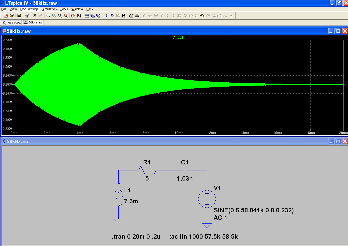
I have an amplified signal at 58kHz being transmitted through a coil antenna. The voltage across the antenna is 1600 volts RMS. A switching circuit is used to clip the ring down of the antenna however I am having a lot of trouble getting the switch to work. Sometimes it does not switch, other times the switch is on during the TX and there is little transmission on the antenna. The switch shorts across the antenna to remove the ring down.

I have tried using a triac (great for current going both ways but at this frequency does not get time to recover so stays on).
Recent attempts are with a pair of TIP50 transistors, another using Mosfets.

If anyone can help with the design, that would be greatly appreciated as this part is critical to completing the project. Has been a thorn in the side for a long time.

Thanks, Robert


Circuit 1.jpg Circuit 2.jpg
 

I see, this is a presistent topic:
https://www.edaboard.com/threads/250785/
https://www.edaboard.com/threads/280017/

Neither of the shown circuits can work, I believe. Besides unsuitable circuit topology, you need switch transistors that can handle more than 2 kV Vce for 1.6 kV Vrms. I'm not aware of FETs or BJTs with sufficient voltage rating. So you would need cascaded switches in series circuit with optocoupler or transformer isolation for the control signal.

Before suggesting alternatives, I would prefer some specification details. What's the point of supressing "ring down"?

According to the resonant topology, the circuit will show a signal envelope with similar attack and decay times. You can even achieve a faster decay by switching the driver phase to 180 degree for a specific time interval. Is it so that you can tolerate slow signal attack but need fast decay? Secondly, what's the available recovery time of a short switch until the next pulse?
Can you give some numbers for L, C and Q?
 
Thanks FvM. There is a separate RX antenna nulled to the TX. I need to remove the TX ring down so I can measure the return signal from a RF tag on the RX.
L = 7.3mH, C = 1.03nF. Not sure about the Q as do not know how to measure (or calculate)
Pulse on time is 4 ms. Off time is 6ms.

The system was working using circuit 2 but it was a fine balancing act between the tuning caps and the resistor and cap before the TIP50. One of the caps shorted out and I have not been able to get it to work since. Figured it better to find a more reliable method to switch.
 

Wind a closely coupled loop or two of wire around your inductors earthy end. This will then act as a transformer and you should be able to use lower rated devices.
In your figure 2, when the RF on the coil goes negative, it forward biases the CB junction, so current flows from the base drive circuit through the collector. I would abandon the single transistor approach. So use two diodes, each feeding a reservoir capacitor, one +, one -. So the RF will charge the caps up in a cycle or two (no load), use your transistors to discharge the caps and hence remove residual energy from the RF. The RF risetime, is dependent on the Q and the impedance of the tuned circuit driver.
Frank
 
Thanks FvM and Frank.
The antenna is a rectangular coil 30cm * 25cm of 80 turns. My diagram was not useful in showing this. Have attached another.
The amplifier is a TDA 7297 - 15W Dual Bridge Amplifier. I am using one channel.
From both yours and FvM's suggestions and insight, I think I need to rethink how to achieve this.

FvM, fast decay time is the key. Would you please advise how the 180 degree signal could be achieved.
Frank, would the transformer approach still work with the rectangular antenna.
Another possibility, could a full wave rectifier and smoothing cap to turn the signal to DC. That would halve the voltage and remove any polarity issues?
I do not know a lot about full wave rectifiers but if it were possible, we could also cascade the switches as you suggested FvM.

Look forward to hearing your thoughts,

Thanks, Robert
 

Attachments

  • Circuit 3.jpg
    Circuit 3.jpg
    27.3 KB · Views: 61

The opposite phase signal would be applied to the amplifier input. Depends on your signal generator design if it can be easily achieved.

One last point. What's the actual amplifier output and coil voltage, without any short switch connected to the LC circuit? This would allow to do a Q calculation
 

1600V???

I would use an optical squib. it is an insulator until a strong laser pulse hits it, then it will conduct.
 

The signal is generated from a AD9851 DDS chip. The 15W audio amplifier produces a 12V p-p signal into the tuning capacitors of the coil.
Without the short switch, the coil has 1600V RMS.

- - - Updated - - -

Hi biff44. I searched for a optical squib but could not find something that is readily available for purchase. Did you have in mind a component that might be suitable?

I found a Q calculator on the net. With this inductance, resistance and frequency, the Q is 332.
 

I modelled a circuit with similar parameters in LTSpice, the envelope should look like below.


If it fits your design, we can use it to test suitable damping and shorting means,
 

Attachments

  • 58kHz.zip
    718 bytes · Views: 57

    V

    Points: 2
    Helpful Answer Positive Rating
So you just need to do Q spoiling? How fast does the coil energy need to ring down?

I'm guessing that you're seeing inconsistent behavior because the switching isn't synchronous with the phase of the antenna current. Ideally you would switch on exactly when the coil current is at zero, but that means the capacitor voltage will be at its maximum, so you would need to deal with a large current pulse.

I think a better solution would be to put the switch in series with the coil rather than in parallel. The switch would be normally on when transmitting, then off to block current. The switch could be a relay or a pair of FETs, protected by a bidirectional TVS in parallel.
 

    V

    Points: 2
    Helpful Answer Positive Rating
First try, use a series switch as suggested by mtwieg and a suitable damping resistor. The switch must be rated for 200V/1A (bipolar). There's a trade-off between switch voltage rating and fast decay.
 

    V

    Points: 2
    Helpful Answer Positive Rating
Second step, proceeding to a practical design with a ground referenced 650V MOSFET.


Not explicitely mentioned, the 5 ohm resistor represents the coil DC + AC(skin effect etc.) resistance, calculated based on the reported voltage numbers.
 

Attachments

  • 58kHz-3.zip
    872 bytes · Views: 40

    V

    Points: 2
    Helpful Answer Positive Rating
sorry I don't know where to buy these laser fired switches, or even if they are available for purchase for non military applications. but here is one link:


- - - Updated - - -

it looks like the thing you want is a "Semiconductor Photoconductive Switch".

https://www.rp-photonics.com/photoconductive_switches.html

specifically the "bulk devices several millimeters or even centimeters long with electrical contacts on the end faces, used for switching very high voltages (sometimes above 100 kV)"
 

Tomorrow I will make a few circuits and test them. See what type of envelop will be interesting.
Will post the results and see what you think.
Robert
 

You didn't tell yet what's the intended envelope. Obviously, if you want a faster settling, you need to increase the drive voltage and reduce the circuit Q.
 
Sorry for not responding for the required envelop.
The envelop needs to have a steep rise and the cut off needs to be as short as possible. Requires about 3 ms of peak TX before turning off.
Is the Q determined by inductance / number of turns on the coil for a given size of coil ?
For example, it I was to increase the number of turns to 120 of a thicker wire to maintain the 8 Ohms resistance for the amplifier, would that increase the Q and voltage across the coil?
Am asking in case I have to increase the field strength.

Did have a result today with the switch but run out of time to take some photos of the wave form.
Will post tomorrow.
Cheers, Robert
 

The relativ slow rising enevelope with the circuit parameters I assumed (you didn't tell yet if the simulation complies with your results), is caused by the high circuit Q, which in turn is linked to the intended resonant voltage boost.

It's very simple to reduce the Q and get faster rise time, but unfortunately, the drive voltage must be increased by the same factor. So this point is completely up to your decision, there's no trick to get faster rise time without a higher drive voltage in the present circuit topology.

You can of course redesign the coil to achieve the same field strength with lower voltage and higher current, probably also requiring a stronger driver. But presently you have set the "1600 Vrms" as a fixed requirement instead of referring to field parameters, so I didn't feel prompted to touch this part of the design.
 
Here are some photos of the ring down.
This is the envelope that I have been looking to attain.

Ring Down 1.jpg

The voltage with the current parameters ~ 1500 PtP. This is without the switching circuit. The ring down as below
RD - 1.jpg


The switch is a 1000V mosfet. A resistor and a Diode are in series into the Drain.
With a 10K Resistor.
RD - 2.jpg


With a 1K Resistor. Signal reduced to 1300V PtP
RD - 4.jpg


Will post a circuit diagram tomorrow as it is very late here.
Thanks
 

Here is the first circuit I tried.
Will try the serial switch tomorrow.

Parallel Switch.jpg
 

Status
Not open for further replies.

Part and Inventory Search

Welcome to EDABoard.com

Sponsor

Back
Top