Continue to Site

Welcome to EDAboard.com

Welcome to our site! EDAboard.com is an international Electronics Discussion Forum focused on EDA software, circuits, schematics, books, theory, papers, asic, pld, 8051, DSP, Network, RF, Analog Design, PCB, Service Manuals... and a whole lot more! To participate you need to register. Registration is free. Click here to register now.

Why SPI LCD not working ?

Status
Not open for further replies.

milan.rajik

Banned
Joined
Apr 1, 2013
Messages
2,524
Helped
540
Reputation
1,078
Reaction score
524
Trophy points
1,393
Activity points
0
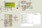
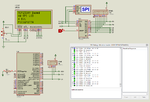
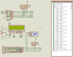
Why SPI Lcd not working. I am using Microchip 8 bit SPI Port expander. The SPI debugger shows that data is sent properly. I am testing it in both Proteus and hardware and it is not working in both. I am using Slaeae Logic Analyzer for testing in hardware. I am using EasyPIC v7 development board.

I am attaching my mikroC PRO PIC project and Proteus file. Proteus file is 8.2 SP2 format. The LCD code is fine because the same code works fine with I2C port expander.

broken link removed
 

Attachments

  • SPI LCD 4 bit.rar
    113.3 KB · Views: 111
  • Spi Lcd 4 bit.png
    Spi Lcd 4 bit.png
    82.6 KB · Views: 275
Last edited by a moderator:

Put the Salae in SPI analysis mode and capture the SPI and LCD control signals as an image so we can see it. Don't worry about the LCD data lines, if the others are correct they will be too. Please label the signals so we can see which they are!

Brian.
 

I removed the hardware setup as I had to test some other project. I will soon setup the hardware again and post the Saleae data. Tell me if there is anything wrong in the values I am writing to the SPI device. I am jsut writing to four registers namely IODIRA, IOCON, GPPUA and OLATA.
 

I do not have the MCP23S09 data sheet with me at the moment to check the commands.

All your software has to do is configure the device to output data and write the LCD bits to it in the correct order. You don't need the SDI signal because in that configuration you can't read the LCD status back anyway, in fact you can ground the RW signal so the LCD is always 'reading' the data you send it.

Don't forget in 4-bit mode you have to do two write operations and you need two changes of pin state for each of them, in other words at least 4 bytes have to be sent to the SPI per character you display.

Brian.
 

I made Soft Spi version of MCP23S09 based SPI LCD and it is working fine in Proteus and also hardware but the hardware Spi version is not working. Why ?

In the earlier code I had forgot to call the
Code:
SPI_LCD_Init();
function.

broken link removed

Damn, the SPI LCD is slow compared to I2C LCD.

- - - Updated - - -

It worked. I changed the SPI_Init() function and it worked. In Proteus it is slow.

broken link removed
 

Attachments

  • MCP23S09 Based Soft SPI LCD.rar
    115 KB · Views: 116
  • MCP23S09 Based HW SPI LCD 4 Bit.rar
    61.9 KB · Views: 92
  • soft spi lcd.png
    soft spi lcd.png
    77.4 KB · Views: 165
  • HW SPI LCD 4 Bit.png
    HW SPI LCD 4 Bit.png
    80.7 KB · Views: 192
  • MCP23S09 Based HW SPI LCD 4 Bit rev1.rar
    117.3 KB · Views: 92
Last edited by a moderator:

Well done!
I gave up on MikroC a long time ago and I have never used Proteus. The compiler I use has a built in debugger that runs at much faster speed, it's difficult to say exactly but on my 3GHz i7 machine it simulates at about 'real time' speed when the PIC clock is about 20MHz.

Brian.
 
@Brian

May I know which PIC Compiler you are using ?
 

I use "Wiz-C MX" from Forest Electronic Developments. **broken link removed**

It has a few 'quirks' and the RAD enviromnent can be a little restrictive for some real-time applications but it can be used as a standard ANSI compiler without the RAD and it is excellent for debugging. The 'PIC Key' it refers to is almost identical in function to a PicKit2/3 although not compatible with them, you don't need it to use the compiler or assembler but if you buy one it fully integrates into the debugging environment. It has really useful feature of being able to program and simulate several PICs (even different types) at the same time so you can make them interact in the simulator. For example you could have one as an I2C master and several as I2C slaves not only see how they talk to each other but debug the code in them both simultaneously. Best of all, it's a fraction of the cost of MikroC or it's other competitors.

Brian.
 
Hi Brian

I have Wiz-C MX and also AVIDICY. The problem is I found the IDE too complicated hence I have never used it. If you have a simple LED Blink project for Win-C Mx then please provide it. I will start learning Wiz-C Mx seriously.
 

It doesn't get much simpler than the attached file.
Hit Alt+D to arrange the window for debugging, it adapts to your screen size/resolution so yours may not match mine.
Unzip the file then open it with "Project/Restore Archive" and check all the boxes. The folder I used is "c:\projects\MilanRajikFlasher" but you can change it when restoring the archive if you want to.
Click the green "Run Simulation" icon to see it in action. It is configured (see app designer) for simulation with the LED cathode to ground and anode via a resistor to RA0 and for 8MHz clock.

Brian.
 

Attachments

  • MilanRajikFlasher_14_06_15.zip
    4 KB · Views: 100
Status
Not open for further replies.

Part and Inventory Search

Welcome to EDABoard.com

Sponsor

Back
Top