Continue to Site

Welcome to EDAboard.com

Welcome to our site! EDAboard.com is an international Electronics Discussion Forum focused on EDA software, circuits, schematics, books, theory, papers, asic, pld, 8051, DSP, Network, RF, Analog Design, PCB, Service Manuals... and a whole lot more! To participate you need to register. Registration is free. Click here to register now.

current sink doesnt work when input to the load is by a regulator

Status
Not open for further replies.

xReM1x

Member level 5
Joined
Mar 25, 2014
Messages
83
Helped
0
Reputation
0
Reaction score
0
Trophy points
6
Activity points
586
hi,
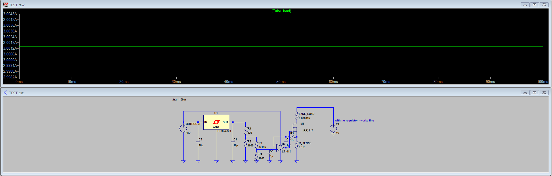
I have a current sink made to vary the current from 0-3A using a potentiometer.
the circuit works great in simulation like this :


but when I add a regulator, as thats what going to happen in my power supply (output of the regulator is going to go to the current sink) this is what happens :


As you can, the current is limited to 1A and the voltage is 110mV. why?
 
Last edited by a moderator:

Thermal overload comes to mind with Vref =1.25V and gain =1+10 =13.75V on top regulator and 30V in makes 16.25 watts at 1 Amp

Bad idea.

Get a OKI/Murata 3 terminal regulator or better use proper CC regulator off the shelf until you learn how to design DC-DC CC regulators.
 
  • Like
Reactions: xReM1x

    xReM1x

    Points: 2
    Helpful Answer Positive Rating
Thermal overload comes to mind with Vref =1.25V and gain =1+10 =13.75V on top regulator and 30V in makes 16.25 watts at 1 Amp

Bad idea.

Get a OKI/Murata 3 terminal regulator or better use proper CC regulator off the shelf until you learn how to design DC-DC CC regulators.

.. what does the regulator has to do with this in simulation? the regulator I used is only for simulation, the real schematic of the regulator is bigger than this.
 

Does the regulator output the expected voltage or not?
no. the regulator output expected voltage is around 13-14V. but for some reason when I connect the regulator to the current sink like I showed (In my final schematic Its not going to be like this, again just for simulation I connect it like this to make im simpler to fix) the voltage drops to ~100mV and the current is limited to 1A. the voltage supposd to be 13-14V and the current ~3A.
.It just doesnt make sense why does it happen with regulator and without regulator (just a voltage source) it doesnt happen.
 

I think it could be a problem of timing. If the mosfet is conducting when the regulator switches on, it sees a short circuit (neglecting Rsense), so it will source 1 A as per data-sheet.
You have to switch it on when the mosfet is not conducting so it can reach the correct operating point.
Of course you'll haven't this problem with the ideal generator.
 

    V

    Points: 2
    Helpful Answer Positive Rating
I think it could be a problem of timing. If the mosfet is conducting when the regulator switches on, it sees a short circuit (neglecting Rsense), so it will source 1 A as per data-sheet.
You have to switch it on when the mosfet is not conducting so it can reach the correct operating point.
Of course you'll haven't this problem with the ideal generator.
so basically I need to add a delay circuit that switchs the regulator output before the mosfet gate opens?
 

well after some playing around (I need relays in ltspice!) I found this working half good :
**broken link removed**
first, It doesnt work if I simulate the supply from 0V. why is that?
also It doesnt work just with 1 transistor so it has to do with the darlington. I found it by mistake, I have no idea whats going on.
also, if I would use a delay to switch Q2 will it work? because when simulating with PULSE 0 5V 0.1s it doesnt work.
 

I can't see the attachement; seems to be invalid
 

I can't see the attachement; seems to be invalid

dd61f7d7414251a9b2b4ea77be49c2cd.png
If it doesnt work
 

The circuit looks strange, the purpose of Q1 and Q2 is mysterious.

A basic constant current circuit would connect the OP output directly to the gate.

- - - Updated - - -

P.S.: Reviewing your initial post, we can just guess that the strange transistors have been added to fix a circuit problem, but you didn't tell what it is. Similar to the problems reported before, I presume it's rather a simulation related than a real circuit problem.

If you want others to reproduce and possibly fix the simulation problems, you should post the LTspice circuits, either zipped or the *.asc files renamed to *.txt.
yes, its indeed strange.

the first LT1083 used as a pre regulator is just for simulation, in the real schematic I'm going to use a switcher as a pre regulator.
the 555 is for the negative rail for the op amp.
 

Attachments

  • 0vlt1083.txt
    7.8 KB · Views: 49

Status
Not open for further replies.

Part and Inventory Search

Welcome to EDABoard.com

Sponsor

Back
Top