Continue to Site

Welcome to EDAboard.com

Welcome to our site! EDAboard.com is an international Electronics Discussion Forum focused on EDA software, circuits, schematics, books, theory, papers, asic, pld, 8051, DSP, Network, RF, Analog Design, PCB, Service Manuals... and a whole lot more! To participate you need to register. Registration is free. Click here to register now.

[ARM] ADC in triple interleaved mode (STM32F407)

Status
Not open for further replies.

vanika

Newbie level 2
Joined
May 27, 2015
Messages
2
Helped
1
Reputation
2
Reaction score
1
Trophy points
3
Activity points
23
Hello !

My problem is to run Triple Mode, and generally want a detailed understanding of its boundary opportunities, see what you can squeeze out of this module, to build some graphics of his work, etc.


Code dot - [expand]
1
2
3
4
5
6
7
8
9
10
11
12
13
14
15
16
17
18
19
20
21
22
23
24
25
26
27
28
29
30
31
32
33
34
35
36
37
38
// setup adc 1
 
ADC1->CR2 |= ADC_CR2_ADON;  // on АЦП 1
ADC1->CR2 |= ADC_CR2_CONT ; // Continuos mode 
ADC1->SQR3 |= ADC_SQR3_SQ1_0;   // select channel 1 for adc 1 (РА1)
ADC1->CR1 &= ~ADC_CR1_RES;  // setup resolution 
ADC1->SQR1 &= ~ADC_SQR1_L;
ADC1->CR2 &= ~ADC_CR2_ALIGN; // allign 'right'
ADC1->CR2 &= ~ADC_CR2_EXTEN;    
//ADC1->CR2 |= ADC_CR2_SWSTART; // run!
 
// setup adc 2
 
ADC2->CR2 |= ADC_CR2_ADON;  // on ADC 2
ADC2->CR2 |= ADC_CR2_CONT ; // Continuos mode 
ADC2->SQR3 |= ADC_SQR3_SQ1_0;   // select channel 1 for adc 2 (РА1)
ADC2->CR1 &= ~ADC_CR1_RES;  // setup resolution 
ADC2->SQR1 &= ~ADC_SQR1_L;
ADC2->CR2 &= ~ADC_CR2_ALIGN; // allign 'right'
ADC2->CR2 &= ~ADC_CR2_EXTEN;    // 
//ADC2->CR2 |= ADC_CR2_SWSTART; // run!
 
// setup adc 3
 
ADC3->CR2 |= ADC_CR2_ADON;  // on ADC 3
ADC3->CR2 |= ADC_CR2_CONT ; // Continuos mode 
ADC3->SQR3 |= ADC_SQR3_SQ1_0;   // select channel 1 for adc  3 (РА1)
ADC3->CR1 &= ~ADC_CR1_RES;  // setup resolution 
ADC3->SQR1 &= ~ADC_SQR1_L;
ADC3->CR2 &= ~ADC_CR2_ALIGN;    // allign 'right'
ADC3->CR2 &= ~ADC_CR2_EXTEN; // 
//ADC3->CR2 |= ADC_CR2_SWSTART; // run!
 
// Triple MODE 
 
ADC->CCR = 0x17; //  Triple MODE 
 
ADC1->CR2 |= ADC_CR2_SWSTART;   // RUN!


Actually, the result is the simultaneous operation of all three ADC, but in the data register Multi Mode CDR can be observed only zeros...
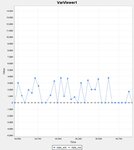
2.jpg

This result is obtained when the input sine wave has a frequency of about 7 kHz. It seems to me that I overlooked in the field sample rate.
Correct if I'm wrong
 
Last edited by a moderator:

Status
Not open for further replies.

Similar threads

Part and Inventory Search

Welcome to EDABoard.com

Sponsor

Back
Top