Continue to Site

Welcome to EDAboard.com

Welcome to our site! EDAboard.com is an international Electronics Discussion Forum focused on EDA software, circuits, schematics, books, theory, papers, asic, pld, 8051, DSP, Network, RF, Analog Design, PCB, Service Manuals... and a whole lot more! To participate you need to register. Registration is free. Click here to register now.

help about usage of optocoupler

Status
Not open for further replies.

istian

Newbie level 6
Joined
Feb 17, 2015
Messages
13
Helped
0
Reputation
0
Reaction score
0
Trophy points
1
Activity points
85
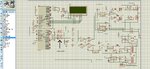
hi every one i am using optocoupler pic817 for my pwm based h-bridge driving circuit. is it a right choice for this circuit...or should i need to replace it with some other package?

one more thing that i want to clear is,currently i am using emiiters output which is being further fed into buffer . so what if i take output from collector?
my circuit diagram is given in attachment
 

Attachments

  • my circuit.jpg
    my circuit.jpg
    366.8 KB · Views: 109
Last edited:

Hi,

you have to read the datasheet.
check the folowing:
* do you have enough drive strength for the optocoupler?
* do you have enough output drive?
* is the delay time (rising and falling) OK for your application?
* is symmetry of rise and fall time important for your application?
* are the isolation parameters (input to output) OK for your application?

***
To the last point:
It seems your input and output of the optocoupler uses the same supply. If this is true, then there is no need for an optocoupler at all.

***

To your circuit:
Be sure to use ceramic capacitors next to the supply pins of each IC. Use a proper ground plane.
The diodes D3, D4, D5, D6 and the relating resistors are useless, because the parallel resistor has much lower impedance than the R-D combination.
C3 and C4 need to be fast ceramic capacitors with short and wide traces.
Depending on switching frequency, FET parameters and load, you may consider external schottky diodes in parallel to your MOSFETS.


Klaus

thanks klausST for this much detailed reply
you didn't tell me what if i take my output from collecter instead of emitter?
 

Hi,

You mean: emitter to GND, collector with pullup? -->
you are free to use emitter or collector. Base is connected internally, so emitter current is the same as collector current.

The only (small) difference is in the effect of capacitive coupling to input side.

Klaus
 

Status
Not open for further replies.

Similar threads

Part and Inventory Search

Welcome to EDABoard.com

Sponsor

Back
Top