Continue to Site

Welcome to EDAboard.com

Welcome to our site! EDAboard.com is an international Electronics Discussion Forum focused on EDA software, circuits, schematics, books, theory, papers, asic, pld, 8051, DSP, Network, RF, Analog Design, PCB, Service Manuals... and a whole lot more! To participate you need to register. Registration is free. Click here to register now.

How to calculate peak voltage of parallel LC tank transient response?

Status
Not open for further replies.

i6power

Newbie level 3
Joined
May 20, 2015
Messages
4
Helped
0
Reputation
0
Reaction score
0
Trophy points
1
Activity points
29
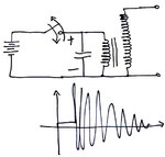
tank_transient.jpg

I spent 2 hours googling, but could not find any useful information on calculating the peak voltage of parallel LC tank transient response.

See the attached circuit diagram. When you open the switch, the current in L wants to keep going, and charges the capacitor, and then capacitor discharges which charges L inductor then they oscillate back and forth, each time reducing magnitude because of parasitic resistance disippating energy. What I want to know is what is the peak voltage of the first "swing"? given the values of L, C, initial voltage and parasitic resistance.

Please do not reply about resonance of LC tank circuit which is discussed in every text book, or LC series configuration.
 

When you open the switch, the inductor starts charging the capacitor.

If H is large, and C is small, then voltage will rise very high. (This assumes there is no ohmic load involved.)

To calculate the first voltage swing, there are formulae, which involve joules. A formula for the inductor, and another for the capacitor.

Kinetic energy is converted to potential energy, then back again.

The equation has to do with:
(a) so many Amperes in so many Henries, equates to...
(b) so many Volts on so many Farads.

You sound very knowledgable. Could you share that formula or point to where I can read about it?
 

So the answer is SQRT (L/C) * I ?
 

I guess so. A more accurate answer would be to take into account the I^2 r losses, as the inductors current must flow through the loss resistance (r) even on the first swing but given a decent working Q, the error should not be too great.
Frank
 

Agree with Vpk=sqrt(L/C)*Ipk .

For an accurate value, take into account the exponential decay of the envelope:

Vpk = sqrt(L/C) * exp(-T/4/tau) * Ipk

For high Q it can be approximated as

sqrt(L/C) * (1-T/4/tau) * Ipk

Z
 

Status
Not open for further replies.

Similar threads

Part and Inventory Search

Welcome to EDABoard.com

Sponsor

Back
Top