ARQuattr
Member level 2
I'm looking to develop a driver that can deliver 12-24VDC over two wires, while having the ability to modulate the output to transmit messages.
Imagine a differential pair bus (like RS-485), but instead of 5V, running at 24V. So when wire A is high (24VDC) and wire B is low (0V) the potential at the receiving end would be 24VDC. This would be the default idle state and the devices attached to this bus can draw power from it. Then wire A may be switched to 0V and B to 24VDC, providing -24VDC to the receiving devices. The bus should deliver at least 3A, but more if feasible.
A communicating device (an MCU) would provide a single-ended UART signal (which is also normally high). When that input goes low (the start bit of the communication), A would go low and B would go high, and so on. The result is just a high-voltage, high-power, differential version of the incoming UART signal.
On the receiving side, the input would be split to recover the message, and also rectified to deliver power.
I tried this with an H-bridge using P and N FETs and gate drivers (FAN3278TMX), but I keep having the gate drivers fail. There is an MCU that controls the inputs to the gate driver to avoid shoot-through conditions and this helps, but when the output is loaded (e.g. a short which the system must be able to tolerate) the drivers often fail. I also have a current limit device (FPF2700) but it doesn't seem to protect it.
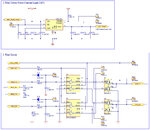
I attached an image of the schematic. This is an older version where I used RC-diode networks to delay inputs to control shoot-through, but this was replaced with an MCU which works much better.
I tried replacing the gate drivers and inputs with ISL83202IPZ, but the nature of the bootstrap capacitor to drive the high side FET doesn't work for me because the FETs are not switching continuously. The FAN3278 drivers have internal gate drive voltage regulators so they can drive the high FETs at any time.
So my main issue currently is that the FAN3278 device seems to fail too easily, and I'm not sure if it's something in the design, or how I'm using it, or if they are just not suitable for the application. I couldn't find other devices that work similar to it.
Does anyone know of another approach I could take to solve this?
Thanks
