Continue to Site

Welcome to EDAboard.com

Welcome to our site! EDAboard.com is an international Electronics Discussion Forum focused on EDA software, circuits, schematics, books, theory, papers, asic, pld, 8051, DSP, Network, RF, Analog Design, PCB, Service Manuals... and a whole lot more! To participate you need to register. Registration is free. Click here to register now.

how to design ebg at 2.4 GHz using suspended line

Status
Not open for further replies.

adel2000

Newbie level 4
Joined
Jul 3, 2011
Messages
5
Helped
0
Reputation
0
Reaction score
0
Trophy points
1,281
Activity points
1,312
Hi all

i am familiar with CST software.
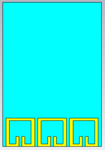
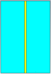
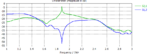
i have a project to design EBG structure using suspended line to get s21 and the phase at 2.4GHz

i dont have any idea to start.

i want to know, is it the suspended line can be
on the substrate
while the ebg structure at the back of substrate like ground
or how?

please help me

your help is highly appreciated
 

Welcome adel2000,

There are several methods used for this test. One is with a microstrip above an EBG ground. One is with a microstrip suspended in air above the EBG surface, which has its own dielectric backing. See for example "A uniplanar compact photonic-bandgap (UC-PBG) structure and its applications for microwave circuit".

The "proper" test will depend on whether or not your EBG has a conductor backing of its own.
 
Thanx a lot PlanarMetamaterials

i am still confusing because i am new to antenna field.

i will show you what i try. i design micrstrip line in front of the substrate and EBG in the back for the same substrate.is this way is correct

also for analysing the badgap, the result base 0n s12 or s21

thanx in advance
 

Attachments

  • back EBG.PNG
    back EBG.PNG
    4.6 KB · Views: 122
  • front micrstrip line.PNG
    front micrstrip line.PNG
    3.5 KB · Views: 125
  • result.PNG
    result.PNG
    13.2 KB · Views: 126

i will show you what i try. i design micrstrip line in front of the substrate and EBG in the back for the same substrate.is this way is correct
also for analysing the badgap, the result base 0n s12 or s21

It's been done that way before, yes. I'm a little surprised by your S-parameters though, why are S21 and S12 so different? They almost appear to be opposites around 1.9 GHz... is "S21" actually S11 or S22?
 

Status
Not open for further replies.

Part and Inventory Search

Welcome to EDABoard.com

Sponsor

Back
Top