Continue to Site

Welcome to EDAboard.com

Welcome to our site! EDAboard.com is an international Electronics Discussion Forum focused on EDA software, circuits, schematics, books, theory, papers, asic, pld, 8051, DSP, Network, RF, Analog Design, PCB, Service Manuals... and a whole lot more! To participate you need to register. Registration is free. Click here to register now.

Pls help me explain this charger circuit

Status
Not open for further replies.

tengyy

Member level 1
Joined
Jul 16, 2014
Messages
32
Helped
0
Reputation
0
Reaction score
0
Trophy points
6
Activity points
201
exp-lantion.JPG


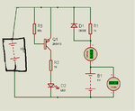
This is a solar energy charger and have a PNP 2N5401 transistor

can anyone explain to me about how this circuit can work ? and the LED can light up when battery is implement.


https://www.onsemi.com/pub_link/Collateral/2N5401-D.PDF
 

Attachments

  • Solar+USB charger.JPG
    Solar+USB charger.JPG
    55.9 KB · Views: 132
Last edited:

Hello tengyy, this circuit is a little weird. Yes when you have a VCC voltage higher than battery's voltage it would charge through 1000 resistor, once VCC is lower than Vbat - Vdiode the battery will discharge through VCC to Gnd. The other part of the circuit will never work because to power the LED the PNP transistor should be at active or saturation region. To achieve this, should pass current through the transistor base and in this circuit this does not happen (unless the transistor let current flow from base to emitter which indicates a fault transistor).
 
  • Like
Reactions: tengyy

    tengyy

    Points: 2
    Helpful Answer Positive Rating
Sorry ya.. maybe this will be easier to see , and thank you for your explanation
Solar+USB charger.JPG
 
Last edited:

Looks like a schematic error to me, or something else is there but missing in the diagram. The battery charges as explained by Yosmany325 but the transistor never conducts. Either something else is connected to it's base pin or Q1 is both the wrong polarity and has it's collector and emitter reversed.

Note that the link you gave to the 2N5401 does not match the transistor in the schematic which is marked 2N5415.

Brian.
 

I am sorry, i just notice the first schematic should be the wrong one. this should be correct
Solar+USB charger.JPG
 

This circuit has two parallel path, one for battery charging and one for LED glowing. battery charging may be work when the solar panel voltage will be more enough may be 18 to 26 volts but other part of LED circuit will never work as it needed -ve base voltage that it will never get.
I have checked this in Proteus. you can see the result when the applied voltage is 22 volts dc than 20 mili amp current is flowing through the battery for charging, but LED still not glowing.
 

Attachments

  • solar charge.jpg
    solar charge.jpg
    106.7 KB · Views: 126

The new schematic makes a little sense but it still won't work.

The top transistor (Q5?) is wired wrongly to be a 5V regulator. It should be wired with the incoming voltage to the collector, +5V taken from the emitter, have the Zener diode from base to GND and the bias resistor from collector to base. Just about everything is wrong!

The LED circuit will light when the battery is on charge although most of the charging current will flow through the base-emitter junctions which is not a good idea. I'm not sure what D1, D2, D3 and D4 are there for, they seem to have no purpose. If they are to protect charging circuits when the power is off but a charged battery is still fitted, the 1.2V from the battery is low enough not to do damage anyway. There is no charge current regulation so either this is a failed attempt at designing a charger or the schematic copied from a poorly designed one.

Given the 5V to start with and the maximum current limited to about 3.2mA, it would make more sense to simply wire the LED in series with the battery.

Brian.
 

Status
Not open for further replies.

Part and Inventory Search

Welcome to EDABoard.com

Sponsor

Back
Top