Continue to Site

Welcome to EDAboard.com

Welcome to our site! EDAboard.com is an international Electronics Discussion Forum focused on EDA software, circuits, schematics, books, theory, papers, asic, pld, 8051, DSP, Network, RF, Analog Design, PCB, Service Manuals... and a whole lot more! To participate you need to register. Registration is free. Click here to register now.

Measurement methods to avoid ground loops

Status
Not open for further replies.

dohzer

Member level 1
Joined
Oct 25, 2008
Messages
39
Helped
0
Reputation
0
Reaction score
0
Trophy points
1,286
Activity points
1,636
I've got a device I need to connect to multiple power supplies and a controller for testing. The device has several modules that all operate off different voltages (12V, 24V and 48V).
The device under test (DUT) has a housing that is used as a common ground point, with all the supplies and controllers connected to it in a star ground configuration via cables (red supply and black ground lines on the diagram).

External to the DUT I need to measure the supply voltages and currents (orange and pink lines on the diagram).
I don't want to create ground loops, so I'm thinking I will need to use differential measurements for each voltage/current signal.
The current measurements will be taken across a shunt resistor.
I have differential ADCs in the controller.

I'm a little overwhelmed with the number of different op-amps and configurations I could use.
General purpose op-amps setup differentially, fully differential op-amps, instrumentation amplifiers.
Single-ended measurement to differential ADC input.
Differential measurement to single ended ADC (negative ADC input grounded).
Differential measurement to differential ADC input?​

What would be the best configuration for this setup?

General setup:
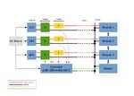
Differential Measurements.jpg
 

Hi,

First thing you have to decide is: What voltage do you need to know?
* the voltage at the DUT, or
* the voltage at the supply
(Often with ATE you need to know the voltage at the DUT, but in your configuration it is the voltage at the supply.)

With your configuration:
You just need an extra GND_sense line to your measurement device.
But don't connect it to the ADC_GND.
You say you have a differential ADC in controller, so there should be a "-" input and a "+" input.
Connect the GND_sense to the "-" input.
Then you don't have a low impedance grond connection, therefore there is no gnd loop.

In case you use a voltage divider and/or a filter at the "+" input of your ADC then use the same at the "-" input.
Mind here to use the ADC_GND.

Klaus
 

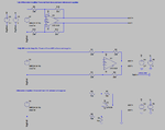
I guess what I'm really asking is what are the differences between, for example, these three setups?

amp config.png

First thing you have to decide is: What voltage do you need to know?
* the voltage at the DUT, or
* the voltage at the supply
(Often with ATE you need to know the voltage at the DUT, but in your configuration it is the voltage at the supply.)
I'm interested in the voltage @ the supply end.[/QUOTE]
 

Using an op amp to measure the supply voltage is purely academic and has no benefit.
Use 2 resistors.
 

Using an op amp to measure the supply voltage is purely academic and has no benefit.
Use 2 resistors.
It depends. The initial post is suggesting common mode errors due to ground voltage drops. If they are relevant, you'll surely need differential amplifiers. But up to now, nothing has been said about expected common mode errors and accuracy requirements. If the requirements are beyond a semiquantitative 10 bit measurement, differential amplifiers should be in fact considered.
 

Hi,

It depends. The initial post is suggesting common mode errors due to ground voltage drops. If they are relevant, you'll surely need differential amplifiers. But up to now, nothing has been said about expected common mode errors and accuracy requirements. If the requirements are beyond a semiquantitative 10 bit measurement, differential amplifiers should be in fact considered.

I don't see a benifit in opamp solution, because the ADC is already differential...

For voltage measurement i'd use two resistors and a capacitor at each input

Klaus
 

It depends. The initial post is suggesting common mode errors due to ground voltage drops. If they are relevant, you'll surely need differential amplifiers. But up to now, nothing has been said about expected common mode errors and accuracy requirements. If the requirements are beyond a semiquantitative 10 bit measurement, differential amplifiers should be in fact considered.
This is true only when the op amp don't introduce any error.
With op amp inputs connected to ground and supply rail you need an extra power supply.
 

For voltage measurement i'd use two resistors and a capacitor at each input
I could agree if I knew more about the ADC parameters.
 

Hi,

Yes, given is just
I have differential ADCs in the controller.
But in detail one need "ADC input voltage range", max gnd bouce range, power supply voltage range(to be measured)...
And so on...

Klaus
 

Hi,

Yes, given is just

But in detail one need "ADC input voltage range", max gnd bouce range, power supply voltage range(to be measured)...
And so on...

Klaus
Klaus and FvM, This could be one of those rare cases that both sides a right.:)
This is the usual straggle between good answer and perfect answer.
If the person that ask the question knew what is all the information needed then he would have known the answer to the question.
To give the perfect answer you need perfect data. In most cases we have to guess most of the missing data and give good answer.
 
Last edited:

The reason I was using the op-amp is that it seems more flexible for signal conditioning.
What if the ADC was ground referenced?
 

The reason I was using the op-amp is that it seems more flexible for signal conditioning.
What if the ADC was ground referenced?
For ground ref ADC you can use resistors dividers for measuring voltages. Use the circuit on post #3 to measure the currents.
 

The reason I was using the op-amp is that it seems more flexible for signal conditioning.
What if the ADC was ground referenced?
I agree with this approach. Even if the ADC has differential imputs, it may still require an amplifier to achieve the common mode voltage specification. Required ADC source impedance is another point that can suggest an amplifier.
 

Easiest solution is quad Op Amp with sense near ground and rail to rail out and low Vio using 50mV current shunt full scale on return side of each leg.

Then use analog MUX into ADC with R scaling to normalize each voltage and current to 100%

You only need one OA for I sense gain=100 or so, non-inverting, with R dividers for each V to Vref/2 or any value to allow for overvoltage, yet give desired resolution with N bit ADC and levels of accuracy.

DO NOT start design until you define, Resolution, accuracy V range, I range for each input in a short spec and then Environmental stress for inputs.

Ensure all Vref measurements use best Star ground otherwise ADC will have missing codes or monoticity errors from ground shift.

Use DAC output to sweep and test ADC vs DAC for calibration errors.
 

Hi,

What if the ADC was ground referenced?

Ground referenced...
1) input voltages?
2) output voltage?
3) supply voltage?

Usually an OPAMP has no true GND connection, Therefore it is not possible for an OPAMP to reference to GND.
Only by dedicated connection of In+ to GND (inverting circuit) or a gain setting resistor to GND (noninverting circuit) it is able to reference to GND.

Klaus

- - - Updated - - -

Hi,

DO NOT start design until you define, Resolution, accuracy V range, I range for each input in a short spec and then Environmental stress for inputs.

Ensure all Vref measurements use best Star ground otherwise ADC will have missing codes or monoticity errors from ground shift.

Yes, yes, yes...

Klaus

- - - Updated - - -

Hi,

For high side current measurement i often use ICs like
ADM4073....
There are a lot of types of different manufacturers...

Klaus
 

Ground Loops:
Differential measurements are an obvious answer and perhaps the right one but another would be to fully isolate your ADC.

Differential measurements logically isolate your measurements from ground loops but don't technically prevent them. Isolation does. All the measurements you want to make share a single ground so you could float the Controller/ADC and use a single wire from the shared ground to reference it. Then the measurements would be single ended.

Though this becomes much less attractive if you have many other signals going to/from the controller which also need to be isolated. In this case an option would be to switch to a discrete ADC which can be independently isolated.

Op-Amps:
In general I have a hard time picturing this circuit without an op-amp for basic buffering and signal conditioning. Op-amps are often more robust and/or cheaper and for that reason alone it can be wise to place them down first in the path. It also leaves open flexibility for hanging off other circuits like comparators without worrying about loading down your measurement signals.


Though finally it would still be helpful to have more context regarding accuracy etc.


Only by dedicated connection of In+ to GND (inverting circuit) or a gain setting resistor to GND (noninverting circuit) ...Klaus


For single supply designs, always use input to Non-inverting single ended input with gain (-) control R to best ground for that circuit.

For long wires use twisted pair and CM choke for remote ground signal sense on remote loads with differential inputs.

Tony
 

dohzer,
You already told us that you want solid ground to all your setup. You also have a Master unit and interconnections. If you break your power supplies grounds to add resistors then it can upset the operation of your setup. It may not work at all if you already use common ground in your power supply. It will also add errors to your voltage readings.
If you use the current measurement from post #3 you wont have to interfere with your grounds connections. You will also need one op amp for each current, the same as required in ground resistors measurements. Your voltage will read the voltage at the supply end as you want.
 

Status
Not open for further replies.

Similar threads

Part and Inventory Search

Welcome to EDABoard.com

Sponsor

Back
Top