Continue to Site

Welcome to EDAboard.com

Welcome to our site! EDAboard.com is an international Electronics Discussion Forum focused on EDA software, circuits, schematics, books, theory, papers, asic, pld, 8051, DSP, Network, RF, Analog Design, PCB, Service Manuals... and a whole lot more! To participate you need to register. Registration is free. Click here to register now.

How to detect Over temprature and / or Open Load in Solenoid Driver BTS716G

Status
Not open for further replies.

dhruv_electro

Advanced Member level 4
Joined
Dec 17, 2010
Messages
118
Helped
9
Reputation
18
Reaction score
8
Trophy points
1,298
Location
India
Activity points
2,378
Hi,
As shown in attachment we are using BTS716G for Solenoid driver. In our design there are 16 solenoid.
The block attached here shows driver for 4 solenoid, other block are ideal to this.
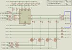
1.jpg

Now our question is how we can detect the Open load error or Over temperature error from a single signal for two channels.
We have seen the Truth table given in datasheet but, we are confuse at how we can detect the error.
Suppose from 16 solenoid if we are going to use on 13 channel then there may be :
1. Channel 1-12 are used identically.
2. Channel 13 is used but its sibling pair Channel 14 is left open always
3. Channel 15 and 16 is also left open always

Now what if channel 13 gets over temperature in field, how can we detect that from Status signal.
What will happen when one channel of two sibling channel pair, is over temperature and other channel is open load?
Please suggest us the logic so we can detect the error in Microcontroller.

Truth table for BTS716G internal logic given in datasheet:

Truth Table BTS716G.jpg

Datasheet for **broken link removed**
 

Hi,

the use of both highside and lowside switch in one circuit makes it difficult.
(i wonder what the idea behind that is...)

usually the BTS716 without the lowside fets should do the job.
The BTS has two status output pins for detecting open load and thermal shutdown.
But then open load detection can not work in combination with the low side switches, becaues they create the "open load" condition even if the solenoid is OK.

For open load connection, the hig side switch should be "open"while the low side switch should be "closed"

1. Channel 1-12 are used identically.
2. Channel 13 is used but its sibling pair Channel 14 is left open always
3. Channel 15 and 16 is also left open always

--> For Open load dectection you need external pullup resistors. The description is very weak on this. (page 9, right column, picture in the middle: R_ext). A 10kOhm to 24V shouldbe OK.

--> You can´t detect which single channel is "open load", the status signal is always a combination of two channels.

--> if only one channel is used, then you should connect a dummy load instead of the unconnected solenoid, to get a "good" status signal. Try 750R, 2W

--> if none of both channels is used then it should be no problem if the status says "open output". That´s the truth.

--> according truth table the "overcurrent" state should be recognized

****
If you need to test every channel individually then you need a more sophisticated solution in combination with software control of the low side switches and a bit of additional hardware.

Klaus
 

Hi Klaus,
Thanks for the help.

the use of both highside and lowside switch in one circuit makes it difficult.
(i wonder what the idea behind that is...)

We have used lower side switch to disconnect not needed Solenoid channels. If in any case we are going to use only 13 channel we are disconnecting 14, 15 and 16 channel with lower switches permanently. We are disconnecting this to separate the GND from any external shorts because sometime external connector pin at Sol_Out_N_x left open without dummies.

But then open load detection can not work in combination with the low side switches, because they create the "open load" condition even if the solenoid is OK.

If we left the channel open we can ignore the error in software as it knows that channel is left open or unused.

For open load connection, the hig side switch should be "open"while the low side switch should be "closed"

--> You can´t detect which single channel is "open load", the status signal is always a combination of two channels.

The problem occurs when we left unused channel in ODD numbers. Like if Channel 1 is used and Channel 2 is left unused and open at lower side. How can we detect if channel 1 solenoid is in good condition, is it open load or over temperature.? and that is why we are confused..:cry::cry::cry:

--> if only one channel is used, then you should connect a dummy load instead of the unconnected solenoid, to get a "good" status signal. Try 750R, 2W

Pain at designer side is no one knows which channel will left open, we needed to detect it in software.

--> according truth table the "overcurrent" state should be recognized

As we have tested with open load (Solenoid is disconnected, Lower FET is ON, Higher BTS Channel is given Input) in BTS716G ignoring the state of error signal, BTS716G getting high temperature, so if you would explain overcurrent detection it would be a pain release. Thanks in advance.

I will also request you to consider if one channel is left open intentionally with lower FET turn off, and input channel at BTS716G continuously low, would it be possible to detect any error in both
 

Hi,

Pain at designer side is no one knows which channel will left open, we needed to detect it in software.
Maybe the designer does not know ... but there must be a person who connects the solenoids to the PCB. He knows where to connect a solenoid, and if there should be no solenoid he should connect a 750R instead.
Is this a possible solution?

As we have tested with open load (Solenoid is disconnected, Lower FET is ON, Higher BTS Channel is given Input) in BTS716G ignoring the state of error signal, BTS716G getting high temperature, so if you would explain overcurrent detection it would be a pain release. Thanks in advance.

Maybe i found a solution to check all:
(connect a 10kOhms pullup on each BTS716G output. This is urgent for open load test.)
- You first need to check on overtemperature.
(if there is an overtemperature condition, then both channels are OFF and there should be no need for check on "open load". If you need an "open load" value, then take the last valid before the overtemperature occured)
- Then you check for CH1 open load
- Then you check for Ch2 open load

To test for high temperature:
* place both channel inputs "H"
* if status shows "low", then an overtemperature occured.

To test for open load CH1: (@ no overtemperature)
* lowside FET CH1 is ON
* highside input CH2 is "high" --> switch is ON (Closed)
* highside input CH1 is "low" --> switch is OFF (OPEN)
--> if now status is "LOW" then there is an "open load" in CH1 condition

To test for open load CH2: (@ no overtemperature)
* lowside FET CH2 is ON
* highside input CH1 is "high" --> switch is ON (Closed)
* highside input CH2 is "low" --> switch is OFF (OPEN)
--> if now status is "LOW" then there is an "open load" in CH2 condition

Klaus
 

Hi Klaus,
Thanks for the reply


Maybe the designer does not know ... but there must be a person who connects the solenoids to the PCB. He knows where to connect a solenoid, and if there should be no solenoid he should connect a 750R instead.
Is this a possible solution?

I will suggest this, but most probably they always deny the solutions which require to connect the component outside of box (PCB container). And if you are saying solutions like "termination resistor" which always suggested in communication like RS485 and CAN, I already have answer from them ("USERS").

(connect a 10kOhms pullup on each BTS716G output. This is urgent for open load test.)

Are you suggesting at pin 13, 14, 17 and 18 here:
Pull up 1.jpg

or at pin 4 and 8 ( I already have)
Pull up 2.jpg

To test for high temperature:
* place both channel inputs "H"
* if status shows "low", then an overtemperature occured.

First of all sorry that I have forgot to mention, for error detection I can not manipulate the Inputs / PWM signal to the pin no 3,5,7 and 9. They are calculated from a specific routine, so I can
1. only wait for both signal to go for "H" and at that moment I can measure status signal for over temperature,
2. if over temperature is not the condition, I will wait for open load conditions one by one as you suggested.
Sure Thanks for that, I will check it and say the result to you later.

But the problem with this is when only one of the channel is in use, the other channel (should be) kept open via lower FETs and input for the respective channel will always be Low.
So what will be value of status signal when the channel which is actove will go for temperature / open load? Will you please help me with that?
 

Hi,

Are you suggesting at pin 13, 14, 17 and 18 here:
Yes. This is to pull the output weakly to 24V. When no load connected, then there will be voltage above 4.0V (highest threshold level of BTS716), with load it will be below 1.7V (lowes threshold level).
This enables the the BTS716 to recognize "no load" condition.

....about 750 Ohms dummy load instead of solenoid:
With my procedure written in post#4, it is not necessary anymore, becauese it checks Ch1 and CH2 independently.
Forget about the 750R, I hope i don´t confuse you now.

First of all sorry that I have forgot to mention, for error detection I can not manipulate the Inputs / PWM signal to the pin no 3,5,7 and 9. They are calculated from a specific routine, so I can
1. only wait for both signal to go for "H" and at that moment I can measure status signal for over temperature,
2. if over temperature is not the condition, I will wait for open load conditions one by one as you suggested.

If the knowledge about "over temperauture" and "open load" is important, then you need to talk to your software engineer to include the function.

only wait for both signal to go for "H" and at that moment I can measure status signal
Check datasheet on the delay times from "input to status feedback". Your software needs to wait, before reading valod status information.

But the problem with this is when only one of the channel is in use, the other channel (should be) kept open via lower FETs and input for the respective channel will always be Low.
So what will be value of status signal when the channel which is actove will go for temperature / open load? Will you please help me with that?
My procedure of post#4 should give always valid status information.

The connected channels show "connected" and the unconnected channels will show "open load".


Klaus
 

Hi,

I have created TT for BTS716G Internal error states, Input to channels and its status output:
BTS716G Truth Table.jpg
Here please consider:
Over Temp : Over temperature error for channel (1=error present, 0=error not present)
Over Load : Over load error for channel (1=error present, 0=error not present)
In: Input to Respective Channel Pin
Status : Common Status output for both channel from IC (1=error not present, 0=error present) (Active Low)

Now if you can see the yellowis lines the cause of the status to be go low(active low) is present in the red box. and it may be any of the channel.
So in above mentioned step 1 how may I decide if One of the channel or Both of the channel have error?
 

Hi,

overtemp is chip related not channel related. So you can´t find out CH1 or CH2.
There are two chips in one package. Chip1 for CH1 and CH2, chip2 for CH3 and CH4.

***
Overtemp is checked when at least one channels is "ON", while "noload" is checked when related channel is "OFF"
Your truth table is wrong in this.

***
Only in "no overtemperature condition" you can check on "no load". (during "overtemperature" both channels show wrong "no load")
For independently detecting "no load" you have to switch one channel ON while the other is OFF. Look at my post #4.
Therfore your truth table is wrong in this. It always shows both channel inputs "1"

Klaus
 
Hi,

Thank you for taking interest this deep.

For Pulling Up 10k at Higher side FETs, Doesn't it provide few miliamps to solenoids when Input PWM is 0%?

Now first of all I am making "Permanent Short Circuit" at Output of BTS716G to generate Over Temperature conditions. Correct me if I am wrong here.

I have created a complete practical test for below Truth Table:

BTS716G Truth Table.jpg

"NA" conditions are which, when Short and Open load condition are present for same channel, as obvious which are not possible. Red indication are cause of error as we think.

Only in "no overtemperature condition" you can check on "no load". (during "overtemperature" both channels show wrong "no load")

I am not getting your point here, in my examination, even if when one of the channel is short circuited and other is open circuited, it gives the status "Active (Low)". Is it like to get Over Temperature error channel must be ON first? Is it why I am getting this?

For independently detecting "no load" you have to switch one channel ON while the other is OFF. Look at my post #4.
Therfore your truth table is wrong in this. It always shows both channel inputs "1"

I am not getting this point, sorry for my slow learning, will you please elaborate this? Also consider newer truth table while helping me out. Thanks for that.

If the knowledge about "over temperauture" and "open load" is important, then you need to talk to your software engineer to include the function.

1. No only the indication of fault condition for particular channel is required. No need to differentiate Open load or over temperature. But as you said for over temperature, we can not differentiate which channel is faulty :bang::bang::bang:

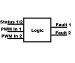
2. My requirement is to design a logic (Software) which takes PWM Input1 , PWM Input 2 and Error Status signal as Input and provide Two Fault 1 and Fault 2 output. I hope I am not confusing here.

Falut Logic BTS716G.jpg
 

Hi,

For Pulling Up 10k at Higher side FETs, Doesn't it provide few miliamps to solenoids when Input PWM is 0%?
Yes, max. 2.4mA. Without current i can't imagine how to detect a load...

I am not getting your point here, in my examination, even if when one of the channel is short circuited and other is open circuited, it gives the status "Active (Low)". Is it like to get Over Temperature error channel must be ON first? Is it why I am getting this?
Because datasheet says that at least one channel input has to be high to test on overtemperature.

I am not getting this point, sorry for my slow learning, will you please elaborate this? Also consider newer truth table while helping me out. Thanks for that.
Please work through the datasheet carefully.
In short: with a high on any input you can check on overtemperature
With a low at a specific input you can check on open load at the relating output.

1. No only the indication of fault condition for particular channel is required. No need to differentiate Open load or over temperature. But as you said for over temperature, we can not differentiate which channel is faulty
Then the check on overtemperture in my procedure is redundant. Just do the two checks on "open load"

2. My requirement is to design a logic (Software) which takes PWM Input1 , PWM Input 2 and Error Status signal as Input and provide Two Fault 1 and Fault 2 output. I hope I am not confusing here.
It's not that easy. A simple combinatorial logic won't work. You need additional delay logic to capture the status signal and timed logic to validate your results.


Klaus
 

Hi Klaus,

Thanks for the reply. I am modifying the upper software routine to include the steps you suggested. It will take some time. I will post the result here.
 

Hi,

Thanks for taking the interest in others pain.

I have just completed software logic and tested it with only software simulation. Yet hardware testing is pending. Just a different approach.

1. I have taken the reading in a single register called "ReadingValue".
Code:
//Here ReadingValue is a copy of last reading
//of pin no 3,5 and 4
//0th bit is INPWM 1 	
//1st bit is INPWM 2
//2nd bit is Status1/2

Here Status1/2 is active low.

Example of Reading value:
Code:
(0x00 : Status1/2 = 0, INPWM2 = 0, INPWM1 = 0)
(0x04 : Status1/2 = 1, INPWM2 = 0, INPWM1 = 0)
(0x05 : Status1/2 = 1, INPWM2 = 0, INPWM1 = 1)
(0x07 : Status1/2 = 1, INPWM2 = 1, INPWM1 = 1)

2. There are below mentioned error state possible for any input
Code:
//Possible error state means
//0 - No Error
//1 - Open Load Channel 1
//2 - Open Load Channel 2
//3 - Open Load Channel 2, Open Load Channel 1
//4 - Open Load Channel 2
//6 - Over Temprature Channel 1,Open Load Channel 2
//8 - Over Temprature Channel 2
//9 - Over Temprature Channel 2, Open Load Channel 1
//12 - Over Temprature Channel 2, Over Temprature Channel 1

3. By close review of TT, I have calculated possible error state for any input:
Code:
Reading Value = 0 -->>Possible Error State = {1,2,3,6,9}
Reading Value = 1 -->>Possible Error State = {2,3,4,6,12}
Reading Value = 2 -->>Possible Error State = {1,3,8,9,12}
Reading Value = 3 -->>Possible Error State = {4,6,8,9,12}
Reading Value = 4 -->>Possible Error State = {0,4,8,12}
Reading Value = 5 -->>Possible Error State = {0,1,8,9}
Reading Value = 6 -->>Possible Error State = {0,2,4,6}
Reading Value = 7 -->>Possible Error State = {0,1,2,3}

Now Say first we received Reading Value = 4
Code:
Reading Value = 4 --> Possible state of error : {0,4,8,12}
In next cycle if we received Reading Value = 5
Code:
Reading Value = 5 --> Common state of error : {0,8}
In next cycle if we received Reading Value = 0
Code:
Reading Value = 0 --> Common state of error : {8}

So finally it state that error is Over Temprature in Channel 2.

Complete C conversion is here View attachment BTS716G Logic.txt

It is bit lengthy, but if you have time please review it. Thanks for that in advance.
 

Status
Not open for further replies.

Similar threads

Part and Inventory Search

Welcome to EDABoard.com

Sponsor

Back
Top